Display method and related device thereof

A display method and a technology of a display device, which are applied in the direction of using projection device image reproducers, static indicators, instruments, etc., can solve the problems of abnormal display brightness, power supply response speed cannot meet the fast adjustment between frames, etc., and achieve contrast improvement and saving , Reduce the effect of the requirement for a faster response speed of the light source

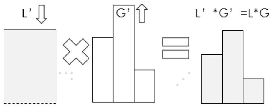
Pending Publication Date: 2022-01-21
APPOTRONICS CORP LTD
View PDF0 Cites 0 Cited by
  • Summary
  • Abstract
  • Description
  • Claims
  • Application Information

AI Technical Summary

Problems solved by technology

[0003] However, in actual use, unless specially designed, the response speed of the commonly used power supply cannot meet the requirements of fast adjustment between frames, especially when using high-brightness light sources, which have dozens or even hundreds of Laser, the total power output of the power supply is as high as thousands of watts
In the power supply design of the high-brightness light source actually used, in some cases, the response speed of the power supply is greater than 50ms, and the single frame duration of the video signal greater than 60Hz is 16.7ms, which leads to abnormal display brightness caused by the current change with time in one frame question

Method used


Image

  • Display method and related device thereof
  • Display method and related device thereof
  • Display method and related device thereof

Examples


Embodiment 1

[0118] The range in which the driving current of the light source changes from the adjustable minimum value to the adjustable maximum value is divided into M grades, and the corresponding current values ​​are I 1 , I 2 ,..., I M , so that the brightness of the light source corresponding to the spatial light modulator is also M-level, that is, the brightness of the corresponding light source is L 1 , L 2 ,...,L M . Adjustment step size ΔI between adjacent current levels m = I m -I m-1 , (m=2,3,...M). During the display time of one frame, the current I m-1 Increase change to I m , or current I m+1 decrease change to I m , that is, the current can change to a stable value I according to the determined waveform m .

[0119] If the maximum value of the gray signal of all pixels in a frame is G max meet L m-1 M · G max ≤ L m , where L M is the maximum light source brightness that can be realized by the display device, then the target light source brightness in ...

Embodiment 2

[0130] This embodiment mainly introduces how to specifically obtain the grayscale mapping relationship table for determining the final grayscale signal of each pixel in each frame.

[0131] Assuming that the duration T of each frame is 16.67ms, the current of the light source can be adjusted in steps of 5 levels, and the response time for adjusting the current between two adjacent levels is about 3.33ms. Switching between the maximum value and the second maximum value corresponds to the The change law of light source brightness is as follows: Figure 9 As shown, among them, Figure 9 The curve equation corresponding to the brightness change curve of the light source in one frame can be expressed as in

[0132] In the process of obtaining the grayscale mapping relationship table, the law of light source brightness variation within a frame can be directly integrated according to the binary grayscale number, so as to determine the actual display brightness corresponding to e...

Embodiment 3

[0139] This embodiment introduces a method for obtaining a grayscale mapping relationship table in a special case.

[0140] Assuming that the change curve of the brightness of the light source is as follows Figure 13 As shown, the change law of the brightness of the light source in a corresponding frame is in

[0141] In this case, the relationship between the grayscale signal and the actual display brightness is as follows: Figure 14 As shown, it can be seen that the actual display brightness no longer increases with the gray signal.

[0142] Sort the actual display brightness with ups and downs from small to large, and get as follows Figure 15 The corresponding relationship between the sorted actual display brightness and the grayscale signal is shown. For this situation, it is necessary to match the expected display brightness corresponding to the initial grayscale signal with the actual display brightness, and use the grayscale signal corresponding to the matched...


PUM


Abstract

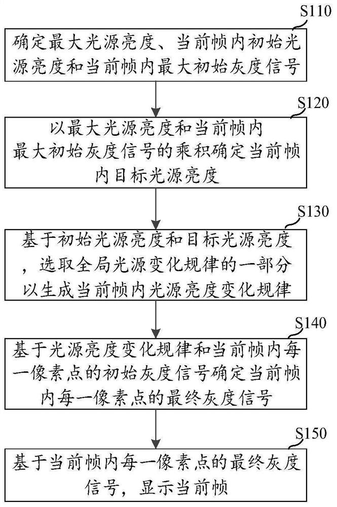
The invention provides a display method and a related device thereof. The display method comprises the following steps: determining the maximum light source brightness, the current intra-frame initial light source brightness and the current intra-frame maximum initial gray level signal; determining the target light source brightness in the current frame according to the product of the maximum light source brightness and the maximum initial gray level signal; based on the initial light source brightness and the target light source brightness, selecting a part of a global brightness change rule to generate a light source brightness change rule in the current frame, and determining a final gray signal of each pixel point in the current frame based on the light source brightness change rule and the initial gray signal of each pixel point in the current frame; or based on the initial light source brightness, the target light source brightness and the initial gray level signal of each pixel point in the current frame, determining the final gray level signal of each pixel point in the current frame by searching the gray level mapping relation table; and displaying the current frame based on the final gray scale signal of each pixel point in the current frame. According to the method, abnormal display brightness possibly caused by current change along with time in one frame is compensated.

Description

technical field [0001] The present application relates to the field of display technology, in particular to a display method and related devices. Background technique [0002] In the prior art, when the maximum brightness of the image to be displayed in one frame is less than the maximum displayable brightness of the projection system, the brightness of the spatial light modulator can be reduced while increasing the grayscale brightness displayed by the DMD to ensure the display on the display screen. The corresponding display brightness of each pixel remains constant. [0003] However, in actual use, unless specially designed, the response speed of the commonly used power supply cannot meet the requirements of fast adjustment between frames, especially when using high-brightness light sources, which have dozens or even hundreds of For lasers, the total output power of the power supply is as high as thousands of watts. In the power supply design of the high-brightness ligh...

Claims


Application Information

Patent Timeline
IPC IPC(8): G09G3/00H04N9/31
CPCG09G3/001H04N9/3102G09G3/00H04N9/31
Inventor 陈晨黄国生余新胡飞李屹
Owner APPOTRONICS CORP LTD
Why Eureka
Try Eureka