Axially-stressed pre-tightening bolt connection strength experiment table and experiment method thereof
A technology of connecting strength and pre-tightening bolts is applied in the field of teaching experimental benches, which can solve the problems of difficult installation of strain gauges, inaccurate experimental results, and unfavorable replacement of the tested piece, etc., so as to facilitate experimental analysis, ensure accuracy, Guarantee the effect of experimental detection accuracy
- Summary
- Abstract
- Description
- Claims
- Application Information
AI Technical Summary
Problems solved by technology
Method used
Image
Examples
Embodiment 1
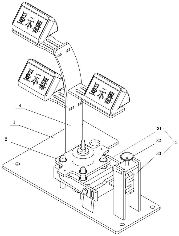
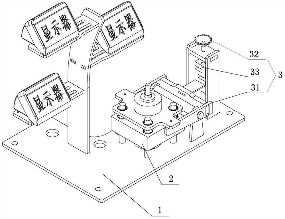
[0076] This embodiment relates to a test bench in static load loading mode. Such as Figure 1 to Figure 8 As shown, the experimental bench includes an experimental bolt connection structure 2 and a loading device 3 arranged on a base 1, wherein the detection elements used include force sensors and deformation displacement detectors, and the displacement detectors use dial gauges. A storage table 4 can also be arranged on the base 1 for placing a display, and the display is connected to the force sensor through the control unit. The specific connection position of the dial indicator is as follows: Image 6 shown.
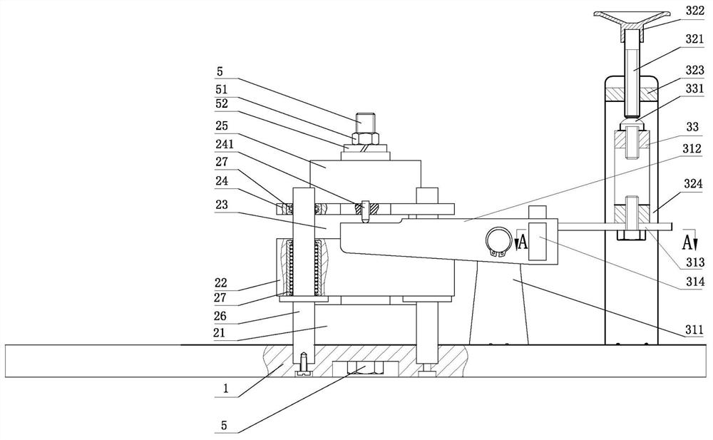
[0077] Such as image 3 As shown, the experimental bolted connection structure 2 includes a sensor A 21, a lower steel plate 22, a connected piece 23, an upper steel plate 24, and a sensor B 25 arranged sequentially from bottom to top. The lower steel plate 22, the connected piece 23, and the upper steel plate 24 There are center holes through the core and the ce...
Embodiment 2
[0097] This embodiment relates to a test bench in a dynamic load loading mode. Such as Figure 9 to Figure 16 As shown, the loading lever and transmission unit of the loading device in this embodiment are different from those in Embodiment 1, and the other structures are the same as in Embodiment 1.
[0098] In this embodiment, the loading lever of the test bench includes a lever bracket 311, a pin shaft 316 arranged on the lever bracket 311, and two lever arms 310 with symmetrical structures at both ends of the pin shaft 316, and the lever arm 310 adopts a rigid beam as a whole. , the right end of the lever arm 310 is fixedly connected with an L-shaped pressing plate 315 . Specifically, the upper end of the vertical plate of the pressing plate 315 is a beam, and the beam is integrally formed with the L-shaped pressing plate 315 , and the two ends of the beam are respectively fixed to the right ends of the two lever arms 310 . Such as Figure 10 to Figure 12 shown.
[0099...
Embodiment 3
[0110]This embodiment relates to a test bench in a dynamic load loading mode. Such as Figure 17 As shown, the difference from Embodiment 2 is that the left lever arm 312 of the loading lever adopts a rigid beam structure with a vertical section, and the right lever arm 313 adopts an elastic beam structure with a certain extension length. The elastic beam is flat and has a cross-section It is rectangular, and the elastic beam is made of elastic material. The right end of the elastic beam is directly connected with the lower end of the sensor C. The experimental bolt connection structure 2, the transmission unit 32, and the sensor C 33 are all the same as those in the second embodiment.
[0111] That is to say, in this embodiment, the structure of the loading lever is the same as that in Embodiment 1.
PUM
 Abstract
Description
Claims
Application Information
 - R&D
- Intellectual Property
- Life Sciences
- Materials
- Tech Scout
- Unparalleled Data Quality
- Higher Quality Content
- 60% Fewer Hallucinations
Browse by: Latest US Patents, China's latest patents, Technical Efficacy Thesaurus, Application Domain, Technology Topic, Popular Technical Reports.
© 2025 PatSnap. All rights reserved.Legal|Privacy policy|Modern Slavery Act Transparency Statement|Sitemap|About US| Contact US: help@patsnap.com


