

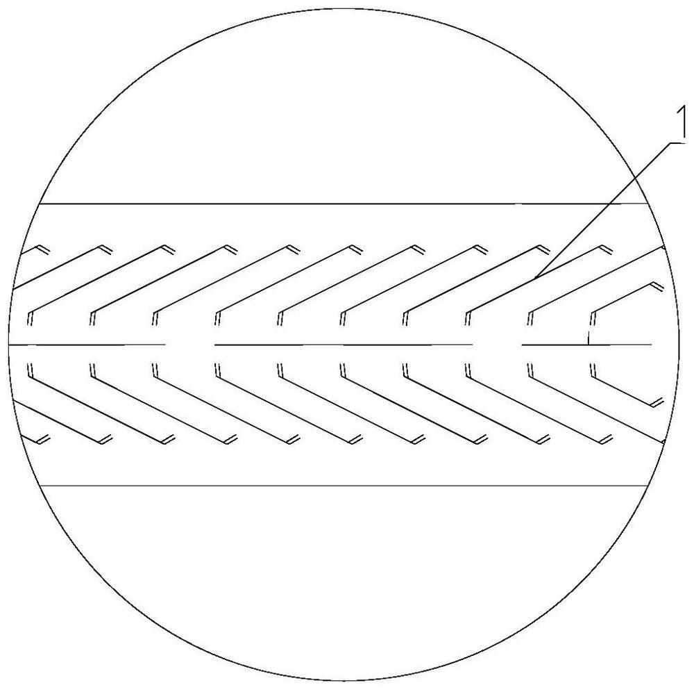
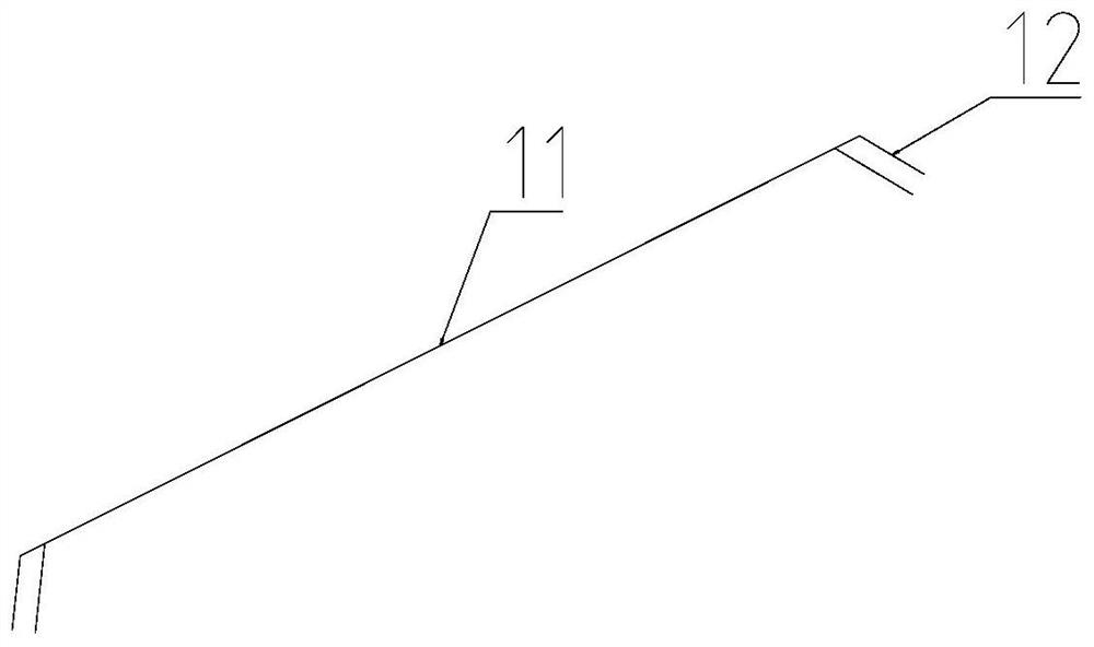
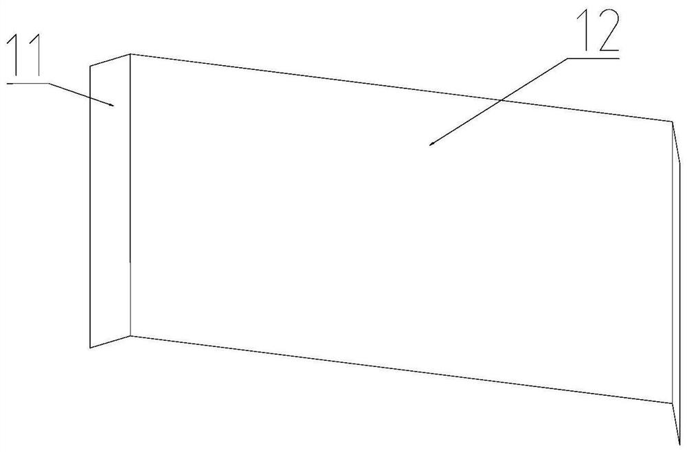
Machining method of die cutting die blade
A technology of die-cutting blade and processing method, applied in metal processing and other directions, can solve the problems of the die-cutting blade cannot be installed normally, reduce work efficiency, etc., and achieve the effect of improving processing efficiency, ensuring smoothness, and preventing the formation of bending parts.
- Summary
- Abstract
- Description
- Claims
- Application Information
AI Technical Summary
Problems solved by technology
Method used
Image

Examples
Embodiment Construction
[0030] In order to make the object, technical solution and advantages of the present invention clearer, the present invention will be further described in detail below in conjunction with the accompanying drawings and embodiments. It should be understood that the specific embodiments described here are only used to explain the present invention, not to limit the present invention.
[0031] In the description of the present invention, it should be understood that the orientation or positional relationship indicated by the terms "upper", "lower", "front", "rear", "inner", "outer" etc. Orientation or positional relationship is only for the convenience of describing the present invention and simplifying the description, and does not indicate or imply that the referred device or element must have a specific orientation, be constructed and operated in a specific orientation, and thus should not be construed as a limitation of the present invention.
[0032] In the description of the...
PUM
 Abstract
Description
Claims
Application Information