
Patsnap Eureka
For R&D, Patsnap Eureka makes reading and utilizing patents & technical documents easy.
Patsnap Eureka AIR
Designed for self-driven R&D workflows. Generate viable solutions, solve complex R&D challenges, empower your innovation with AI.

Patsnap Eureka Materials
Designed for material experts only. Revolutionize your material R&D, from search, analyze, to developing new materials.

TechResearch
Generate reliable direction feasibility study reports for your R&D in just a few steps.

TechSeek
Discover and master advanced knowledge NOW. Basics, ideas, possibilities, all at once.

TechMind
As an expert in R&D Theories, TechMind can generates customized viable solutions instantly.

TechRisk
Analyze your overall solution with one click, know your potential R&D risks in advance.

TechMonitor
Get weekly tech updates, stay abreast of the latest tech innovations and key insights.
Ship T-shaped row clamping device and T-shaped row hoisting method
A clamping device, ship technology, applied in the direction of transportation and packaging, load hanging components, etc., can solve the problems of labor and time, increase the workload of welding and removing lifting lugs, damage to the hull structure, etc., achieve convenient use, reduce burns The effect of reducing welding and cutting workload and reducing potential safety hazards
- Summary
- Abstract
- Description
- Claims
- Application Information
AI Technical Summary
Problems solved by technology
Method used
Image

Examples
Embodiment 1
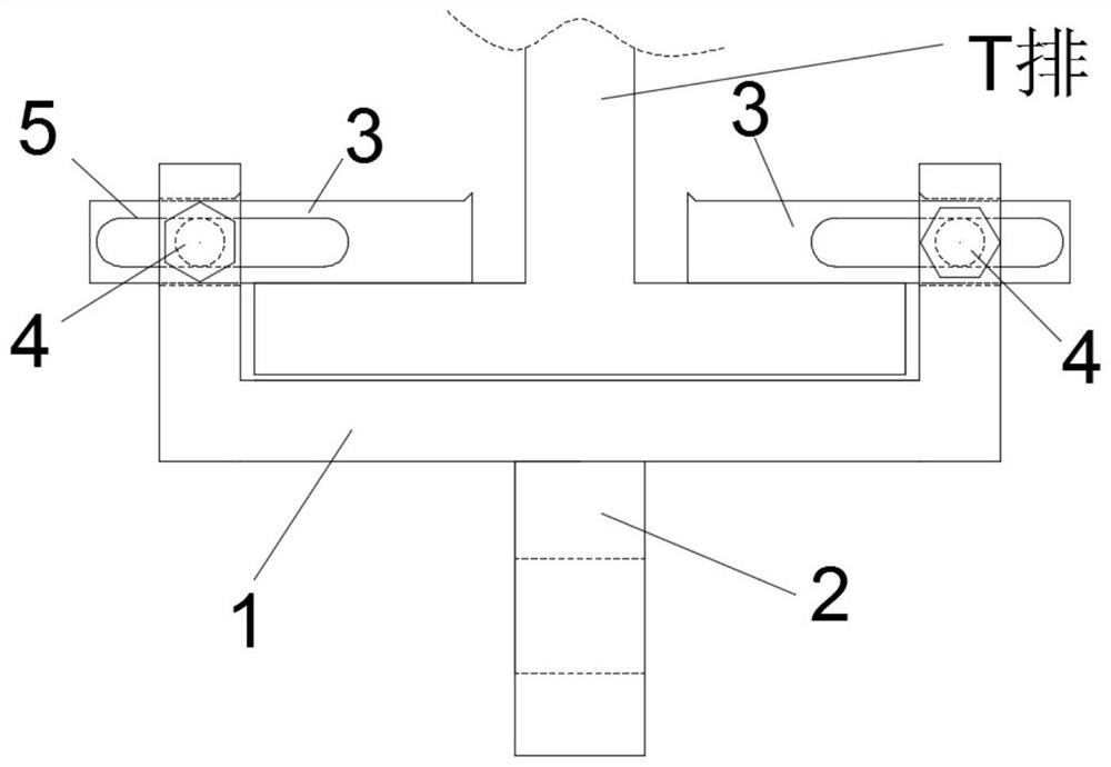
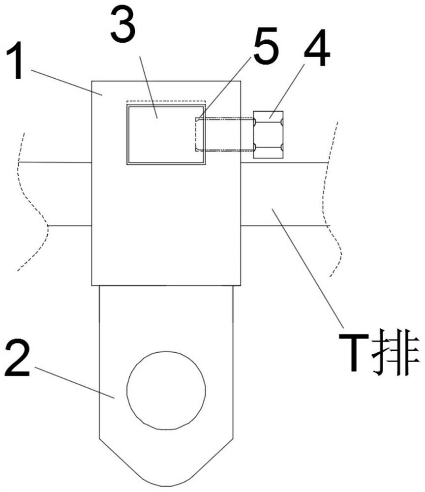
[0026] This embodiment provides a T-bar clamping device for a ship, which includes a U-shaped frame 1, a sliding clamp 3 and a limit bolt 4. The U-shaped frame 1 is welded by steel plates, and the U-shaped frame 1 is U-shaped. The two side walls of the U-shaped frame 1 are provided with holes, and the holes are used for the sliding clamp 3 to pass through, and the front ends of the two sides of the U-shaped frame 1 are provided with threaded holes. The threaded hole is in communication with the hole groove, the limit bolt 4 is fitted in the threaded hole, the sliding clamp 3 is provided with a strip-shaped limit groove 5 along the length direction, and the limit bolt 4 The end of the upper part is engaged in the limiting groove 5, and the lifting eye plate 2 is welded on the bottom plate of the U-shaped frame 1, and the lifting eye plate 2 is welded on the center position of the bottom plate of the U-shaped frame 1. The distance between the sliding clamping plate 3 and the bot...
Embodiment 2
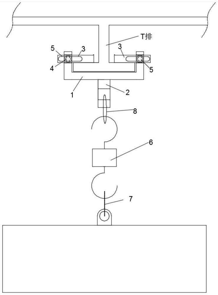
[0030] This embodiment mentions the application of the clamping sling of the T row of the ship. The clamping sling is clamped on the T row, the rope 8 passes through the lifting eye plate 2, the hook of the chain block 6 is hung on the rope 8, and the chain block 6 hooks for lifting heavy objects.
[0031] This embodiment includes the following steps:
[0032] Step 1. Make the ship T row clamping spreader
[0033] The clamping sling includes: a U-shaped frame 1 , a sliding pallet 3 , a limit bolt 4 , and a lifting eye plate 2 . A lifting eye plate 2 is arranged under the U-shaped frame 1, and the U-shaped frame 1 is stuck on the T row through the sliding of the sliding clamp 3, and the sliding clamp 3 is fixed by the limit bolt 4 , realizing the clamping function and the hanging object function of the T-row clamping spreader on the T-row.
[0034] The U-shaped frame 11 is welded by steel plates and is in a "U" shape. Grooves are provided on both side panels of the U-shaped ...
PUM
 Abstract
Description
Claims
Application Information
 - R&D Engineer
- R&D Manager
- IP Professional
- Industry Leading Data Capabilities
- Powerful AI technology
- Patent DNA Extraction
Browse by: Latest US Patents, China's latest patents, Technical Efficacy Thesaurus, Application Domain, Technology Topic, Popular Technical Reports.
© 2024 PatSnap. All rights reserved.Legal|Privacy policy|Modern Slavery Act Transparency Statement|Sitemap|About US| Contact US: help@patsnap.com