Wind-resistant landscape design green belt

A landscape design and green belt technology, applied in protective equipment, general water supply conservation, roads, etc., can solve problems such as device rollover, pedestrian and vehicle hazards on the road, and ground pollution, so as to avoid rollover, improve stability, and reduce pollution. Effect of small obstructed area

Active Publication Date: 2022-01-28
HUNAN UNIV OF ARTS & SCI
View PDF6 Cites 2 Cited by
  • Summary
  • Abstract
  • Description
  • Claims
  • Application Information

AI Technical Summary

Problems solved by technology

[0004] The purpose of the present invention is to provide a wind-resistant landscape design green belt, which solves the problem that in the face of heavy rain and strong wind, the strong wind will generate a large thrust on the sound insulation board and the display board, which will easily cause the device to roll over and the soil at the lower end to turn over. Technical problems that pollute the ground and cause harm to pedestrians and vehicles on the road

Method used


Image

  • Wind-resistant landscape design green belt
  • Wind-resistant landscape design green belt
  • Wind-resistant landscape design green belt

Examples


Embodiment 1

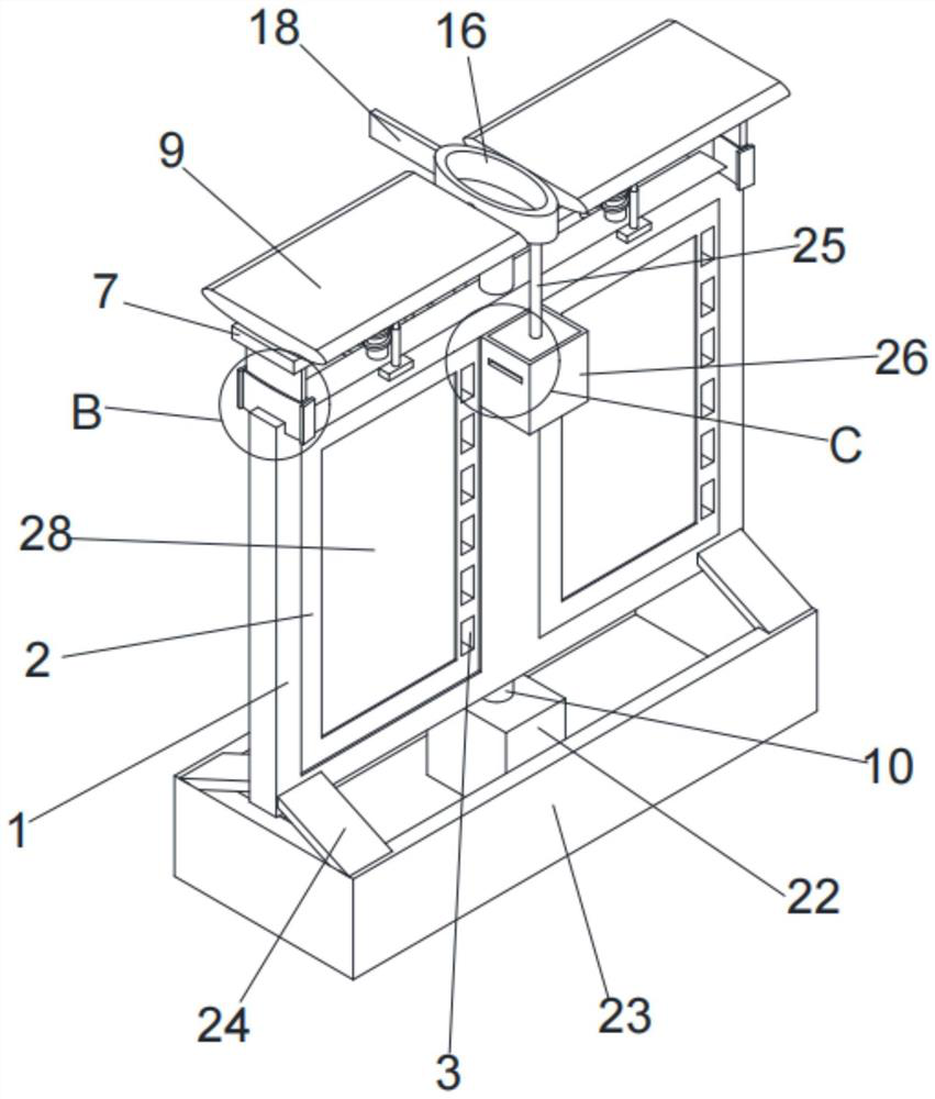
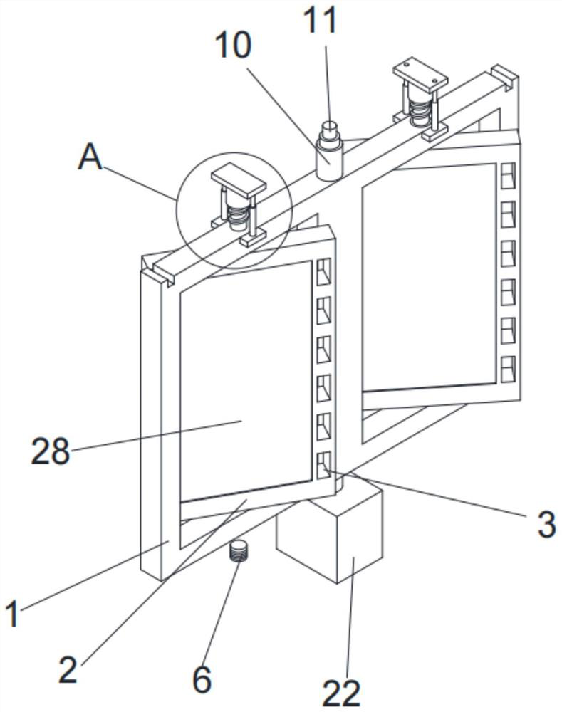
[0029] see Figure 1-Figure 4 , the present invention provides a technical solution, including a fixed plate 1, the left and right ends of the front side of the fixed plate 1 are opened through openings, and the inner wall of the opening is rotatably connected with a rotating plate 2, and the right end of the front side of the rotating plate 2 is opened. There is a ventilation groove 3, the upper surface of the fixed plate 1 is connected with a connecting shaft 4 for rotation, the center of the upper and lower surfaces of the rotating plate 2 is provided with a through hole, and the lower end of the circumferential side of the connecting shaft 1 runs through the passage of the rotating plate 2 for fixed connection. On the inner wall of the hole, the upper end of the circumferential side of the connecting shaft one 4 is provided with a tooth groove 5, and the lower end of the connecting shaft one 4 is fixedly connected with a spring shaft 6, and the lower end of the spring shaft...

Embodiment 2

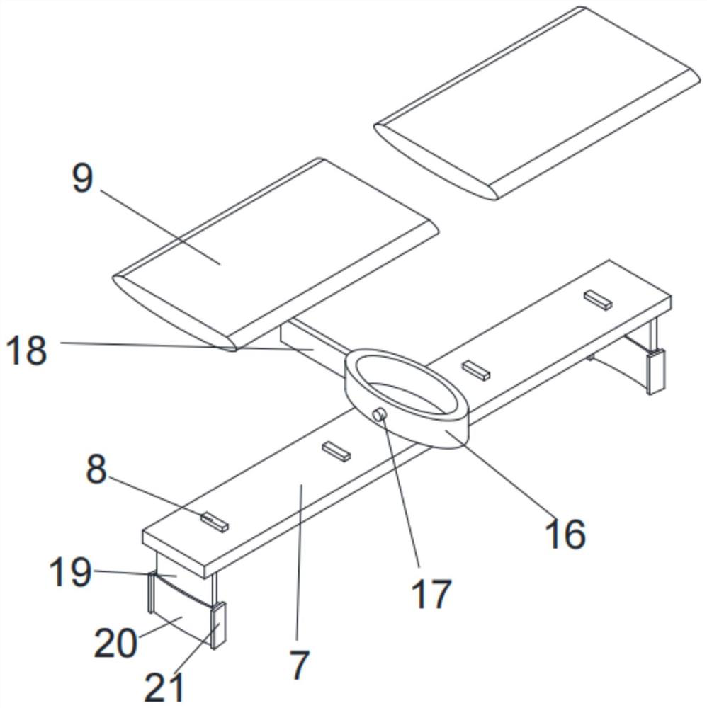
[0032] see figure 1 , image 3 and Figure 5 , on the basis of Embodiment 1, the present invention provides a technical solution: the center of the upper surface of the top plate 7 is fixedly connected with a water collection pipe 16, and the left and right ends of the water collection pipe 16 are fixedly connected with connecting rods 17, and the connecting rods 17 are far away from One end of the water collecting pipe 16 is fixedly connected to the side of the deflector 9. The cross-sectional shape of the water collecting pipe 16 is oval. Limit plate one 19, the lower end of limit plate one 19 runs through and slides to connect limit plate two 20, the front and rear ends of limit plate two 20 are all fixedly connected with side baffle plate 21, the upper surface left and right ends of fixed plate 1 are A chute is provided, and the lower end of the limiting plate 20 runs through the inner wall of the chute that is slidably connected to the fixed plate 1 .

[0033] In this ...

Embodiment 3

[0035] see Figure 1-Figure 2 On the basis of Embodiment 1, the present invention provides a technical solution: the lower end of the connecting shaft 10 is rotatably connected to a base 22 through bearings, the lower surface of the base 22 is fixedly connected to a bottom bin 23, and the front and rear sides of the fixed plate 1 Both left and right ends are fixedly connected with connecting plates 24 , and the lower ends of the connecting plates 24 are fixedly connected with the upper surface of the bottom bin 23 .

[0036] In this embodiment: the bottom bin 23 is filled with soil, which can increase the weight of the bottom of the device while satisfying greening, reduce the center of gravity and improve stability, and after rain, rainwater flows into the bottom bin 23 and is absorbed by the soil, further Increased weight increases stability.


PUM


Abstract

The invention discloses a wind-resistant landscape design green belt, and relates to the technical field of greening facilities, the wind-resistant landscape design green belt comprises a fixed plate, through holes are formed in the left and right ends of the front side surface of the fixed plate in a penetrating manner, rotating plates are rotatably connected to the inner walls of the through holes, and ventilation slots are formed in the right ends of the front side surfaces of the rotating plates in a penetrating manner; the upper surface of the fixed plate is rotatably connected with a first connecting shaft in a penetrating mode, a through hole is formed in the center of the upper surface and the center of the lower surface of the rotating plate in a penetrating mode, the lower end of the circumferential side face of the first connecting shaft is fixedly connected with the inner wall of the through hole of the rotating plate in a penetrating mode, and a tooth groove is formed in the upper end of the circumferential side face of the first connecting shaft; a spring shaft is fixedly connected with the lower end of the first connecting shaft, the lower end of the spring shaft is fixedly connected with the inner wall of the lower side of the through opening of the fixed plate, and the technical problems that in rainstorm and windy weather, strong wind generates large thrust on the sound insulation plate and the display plate, the device is prone to turning over on one side, soil at the lower end is turned up to pollute the ground, and pedestrians and vehicles on the road are harmed are solved.

Description

technical field [0001] The invention relates to the technical field of greening facilities, in particular to a wind-resistant landscape design green belt. Background technique [0002] The green belt refers to the strip-shaped belt for greening, which is directly set in the middle of the road or on the side of the road. It is built by reserving the land required for the construction of the green belt when building the road, and then directly planting plants on the land. , In order to prevent the soil on the green belt from entering the road, the design of the green belt is higher than the ground, and the green belt can also play the role of noise isolation. [0003] For example, according to the "green belt of ecological garden landscape design" provided by the Chinese Patent Authorization Announcement No. CN 113079861 A, by setting sound insulation boards, the effect of sound insulation can be effectively played on the surrounding houses, and display boards can be set to im...

Claims


Application Information

Patent Timeline
Patent Type & Authority Applications(China)
IPC IPC(8): E01F15/02E01F7/02E03B3/02
CPCE01F15/02E01F7/02E03B3/02Y02A20/108
Inventor 温瑞芬吴丹粟媛
Owner HUNAN UNIV OF ARTS & SCI
Why Eureka
Try Eureka