Parking power platform applied to plane moving type parking equipment
A kind of parking equipment and mobile technology, which is applied to vehicle cleaning equipment, buildings where cars are parked, and vehicle cleaning, etc. It can solve the problems of inconvenient parking for novice drivers, no cleaning of car tires, and easy contamination with mud. Achieve the effect of reducing the process of manual cleaning, reducing the difficulty of parking, and reducing waste
- Summary
- Abstract
- Description
- Claims
- Application Information
AI Technical Summary
Problems solved by technology
Method used
Image
Examples
Embodiment 1
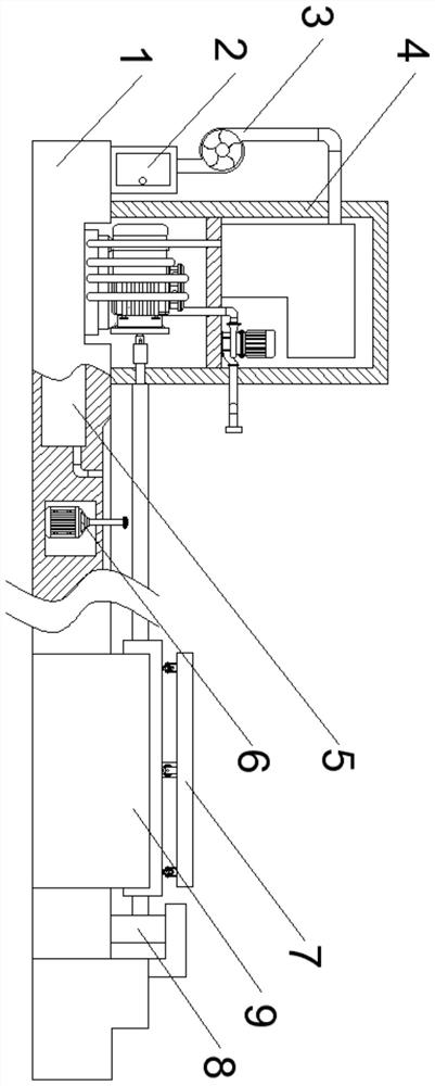
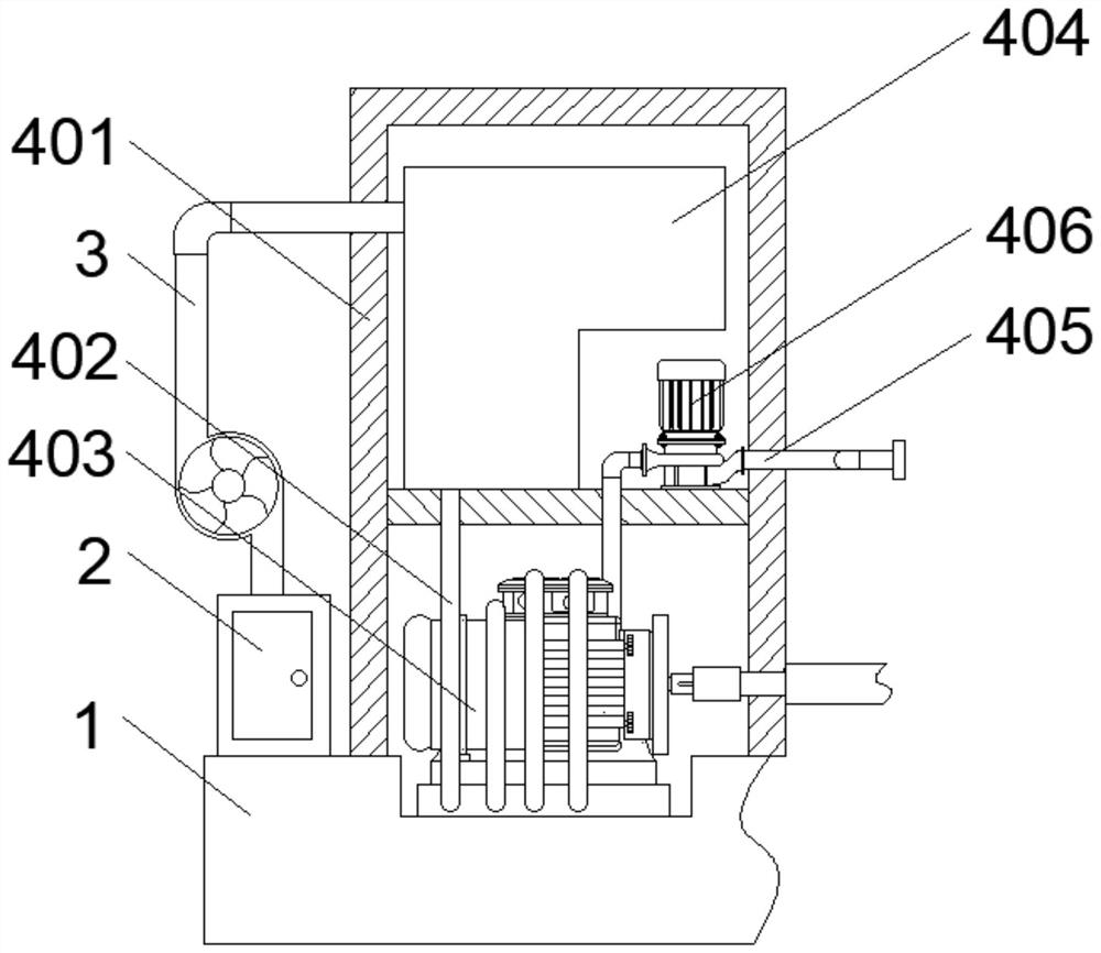
[0031] see figure 2 As shown, the above-mentioned transmission mechanism 4 includes a housing 401 fixedly connected to the base plate 1, a cavity is provided inside the housing 401, a partition plate is fixedly connected to the middle of the cavity, and a water storage tank 404 and a water storage tank 404 are fixedly installed on the top of the partition plate A water pump 406, the output end of the water pump 406 is connected with a water spray pipe 405, the output end of the water spray pipe 405 runs through the casing 401 and is fixedly installed with two nozzles, the bottom of the cavity of the casing 401 is fixed with a servo motor 403 by bolts, A hose 402 communicates with the bottom of the water storage tank 404 , and the hose 402 is wound around the servo motor 403 .
[0032] Through the water pump 406 and the hose 402, the clean water in the water storage tank 404 is drawn out, and then the clean water is sprayed on the tires of the car through the water spray pipe ...
Embodiment 2
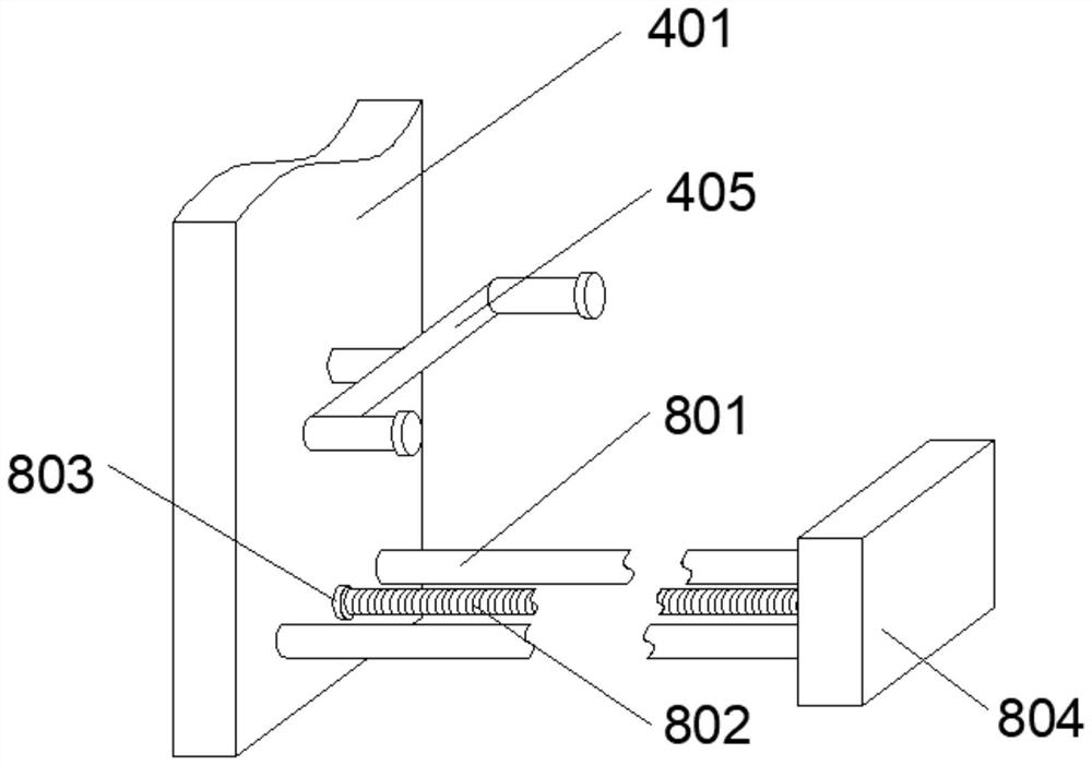
[0034] see image 3 As shown, the above-mentioned guide mechanism 8 includes a limiting plate 804 fixedly connected to the bottom plate 1, two guide rods 801 are fixedly connected between the limiting plate 804 and the casing 401, and the side of the limiting plate 804 facing the casing 401 passes through the bearing A threaded rod 802 is rotatably connected, and one end of the threaded rod 802 is fixedly connected with a coupling 803 . The coupling 803 moves through the casing 401 and is fixedly connected with the output end of the servo motor 403 .
[0035] see Figure 4 As shown, the above-mentioned steering mechanism 6 includes a drive motor 603 fixedly connected to the inner wall of the installation cavity of the base plate 1. The output end of the drive motor 603 is fixedly connected to a first rotating shaft 602, and the top end of the first rotating shaft 602 moves through the base plate 1 and is fixedly connected. There is a first spur gear 601 .
[0036] see Figu...
Embodiment 3
[0039] see figure 2 As shown, a filter box 2 is fixedly installed on the side of the housing 401 far away from the support plate 701, the top of the filter box 2 is connected to a water inlet pipe 3, a water pump is installed in the middle of the water inlet pipe 3, and the output end of the water inlet pipe 3 runs through the housing 401 And communicate with the water storage tank 404, the front end of the filter box 2 is hinged with a sealed door, one end of the water storage chamber 5 is connected with a sewage pipe, the top surface of the bottom plate 1 is provided with a groove corresponding to the position of the nozzle, and the input of the sewage pipe The end and the groove communicate with each other, and the other end of the water storage chamber 5 communicates with the filter box 2 through a connecting pipe.
[0040] Collect the sewage after cleaning the tires through the groove, cooperate with the sewage pipe to suck the sewage into the water storage chamber 5, an...
PUM
 Abstract
Description
Claims
Application Information
 - R&D
- Intellectual Property
- Life Sciences
- Materials
- Tech Scout
- Unparalleled Data Quality
- Higher Quality Content
- 60% Fewer Hallucinations
Browse by: Latest US Patents, China's latest patents, Technical Efficacy Thesaurus, Application Domain, Technology Topic, Popular Technical Reports.
© 2025 PatSnap. All rights reserved.Legal|Privacy policy|Modern Slavery Act Transparency Statement|Sitemap|About US| Contact US: help@patsnap.com


