Power load control system and method combined with electricity measuring device

A technology of power load and control system, applied in the direction of power network operating system integration, circuit device, emergency protection circuit device, etc., can solve the hysteresis of grid response, no matching improvement plan for power measurement device, and no plan for power load control system and other problems to achieve the effect of optimizing the distribution and quantity

Inactive Publication Date: 2022-01-28
STATE GRID SHANDONG ELECTRIC POWER CO WUCHENG POWER SUPPLY CO +1
View PDF6 Cites 0 Cited by
  • Summary
  • Abstract
  • Description
  • Claims
  • Application Information

AI Technical Summary

Problems solved by technology

In the past, the power measuring devices were often processed after the event, and when a fault occurred, there was a serious lag in the response of the power grid; more and more predicted values ​​obtained through training on historical data in advance have appeared in the national grid system, but in the power load There is no related plan on the control system, and there is no supporting improvement plan for the electrical measuring device

Method used


Image

  • Power load control system and method combined with electricity measuring device
  • Power load control system and method combined with electricity measuring device
  • Power load control system and method combined with electricity measuring device

Examples


Embodiment 1

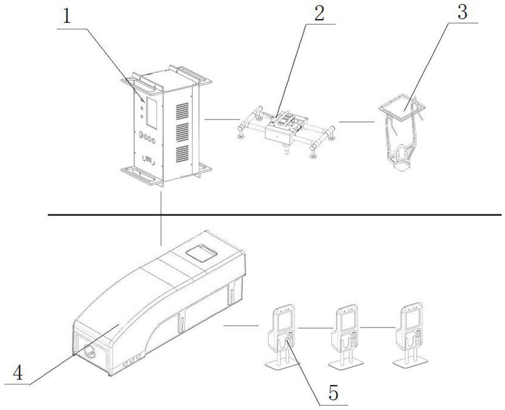
[0036] like figure 1 As shown, the power load control system combined with the power measuring device according to the present invention includes:

[0037] The power main control box 4 is used to determine the historical data of the power load control system 1 through the induction current parameter through the non-contact induction of the induction current parameter in the intelligent terminal 5;

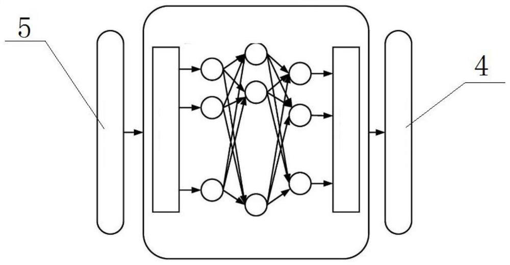
[0038] The induced current parameters and historical data are used as the basic training to obtain the prediction model. The prediction model is divided into convolutional neural network and recurrent neural network. figure 2 shown;

[0039] The power measuring device 3 includes a power measuring module, a processing module, and a load calculation module, wherein:

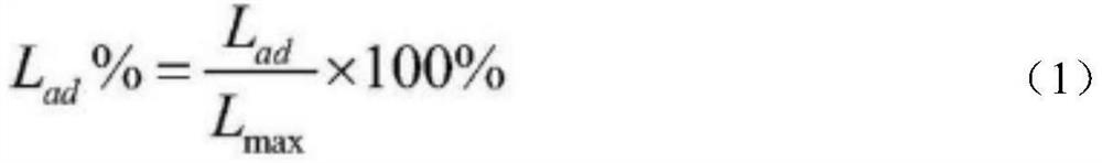
[0040] The power measurement module obtains the initial signal of the load, processes the initial signal through the processing module, and outputs a valid pulse signal, and the load calculation module performs the l...

Embodiment 2

[0057] The power load control method combined with the power measuring device according to the present invention includes the following steps:

[0058] The intelligent terminal 5 transmits the induced current parameters to the power main control box 4 through non-contact;

[0059] The power main control box 4 constructs a prediction model according to historical data and induced current parameters, and further divides the convolutional neural network and the cyclic neural network according to the neural network algorithm to provide current parameters for the power load control system 1;

[0060] A differential protection device is arranged between the circuit breaker 2 and the power measuring device 3, and the accurate load value is measured by using the networking characteristics of the differential protection device;

[0061] The power load control system 1 provides the following actions according to the current parameters given by the prediction model, the load value given ...


PUM


Abstract

The invention relates to a power load control system and method combined with an electricity measuring device, and belongs to the technical field of electrical instruments and meters. The system comprises an electric energy master control box, an electricity measuring device andcircuit breakers ; the electric energy master control box is used for determining historical data of a power load control system through induction current parameters in a non-contact induction intelligent terminal; the electricity measuring device comprises an electricity measuring module, a processing module and a load operation module; the circuit breakers are arranged at the power grid nodes of each region of the power distribution network, realize information interaction with the power load control system and control circuit break, and are connected with the electricity measuring devices to be provided with differential protection devices; and the power load control system obtains current parameters from the prediction model of the electric energy main control box, and starts a circuit breaker when a warning line is reached according to the working load value of the load obtained by the electricity measuring device, and disconnects the connection between the load and the power grid node. By optimizing the distribution and the number of the electricity measuring devices, accurate energy conservation and emission reduction are achieved, electricity is limited for large-power-consumption users, and the healthy development concept is promoted.

Description

technical field [0001] The invention relates to a power load control system and method combined with a power measuring device, belonging to the technical field of electrical instruments. Background technique [0002] With the advancement of technology, the data detected by electrical instruments can be effectively used for prediction and mining, which can play a very critical role in power load control. In the past, the power measurement devices were often processed after the event, and when the fault occurred, the grid response had a serious lag; the predicted value obtained through training with historical data in advance has appeared in the national grid system more and more, but in the power load. There is no relevant scheme on the control system, and there is no matching improvement plan for the power measuring device. With the emergence of measures such as energy conservation and emission reduction, and power curtailment in various places, a technical solution that co...

Claims


Application Information

Patent Timeline
Patent Type & Authority Applications(China)
IPC IPC(8): H02J3/14H02J3/00H02H7/26H02H3/08
CPCH02J3/144H02J3/003H02H7/26H02H3/08H02J2203/20Y02B70/30Y02B70/3225Y04S20/222Y04S20/242
Inventor 杜云陈瑞东袁桂福郭扬范文博刘金金施慧玲芦小龙燕春花姜维壮
Owner STATE GRID SHANDONG ELECTRIC POWER CO WUCHENG POWER SUPPLY CO
Why Eureka
Try Eureka