
Flexible inner wall floating grinding table

A grinding table and flexible technology, applied in the directions of grinding machines, grinding workpiece supports, grinding machine parts, etc., can solve the problems that the dust suction port is easy to block the line of sight, the labor intensity of workers is high, and the adsorption effect is not good, and it can achieve a good blocking effect. Dust effect, realize automatic processing, good effect of dust removal

Active Publication Date: 2022-02-01
浙江君睿智能装备有限公司
View PDF16 Cites 0 Cited by
  • Summary
  • Abstract
  • Description
  • Claims
  • Application Information

AI Technical Summary

Problems solved by technology

[0004] The purpose of the present invention is to provide a flexible inner wall floating grinding table to solve the problem that the existing residues in the pipes and grooves proposed in the background technology are irregular, and generally need to be cleaned manually during the cleaning process, and the labor intensity of workers is high. Large, slow cleaning speed. At the same time, the dust needs to be absorbed by the vacuum table during cleaning, but the vacuum port is easy to block the line of sight, so a certain distance is required between the dust suction port and the operating part, and the adsorption effect is not good, resulting in dust diffusion. The problem of polluting the environment

Method used


Image

  • Flexible inner wall floating grinding table
  • Flexible inner wall floating grinding table
  • Flexible inner wall floating grinding table

Examples


Embodiment Construction

[0064] The following will clearly and completely describe the technical solutions in the embodiments of the present invention with reference to the accompanying drawings in the embodiments of the present invention. Obviously, the described embodiments are only some, not all, embodiments of the present invention.

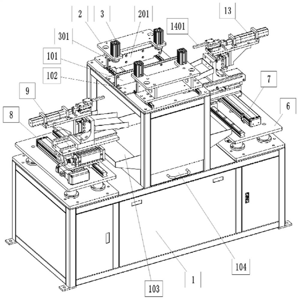
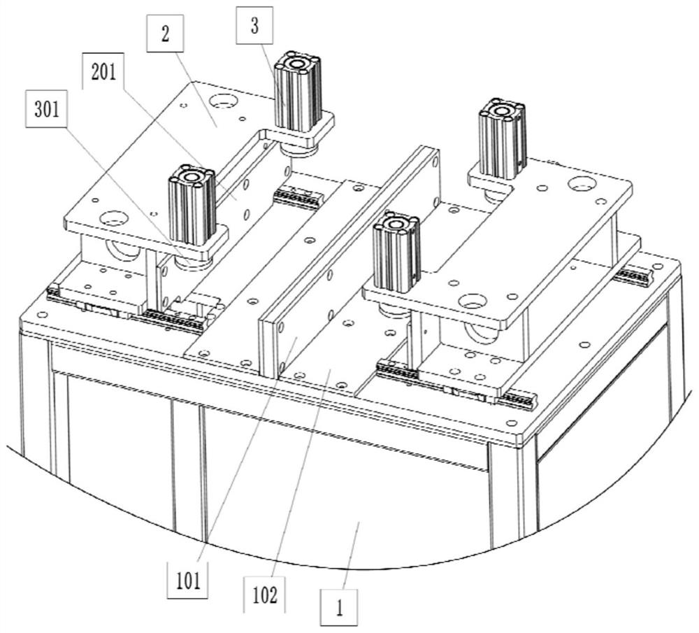
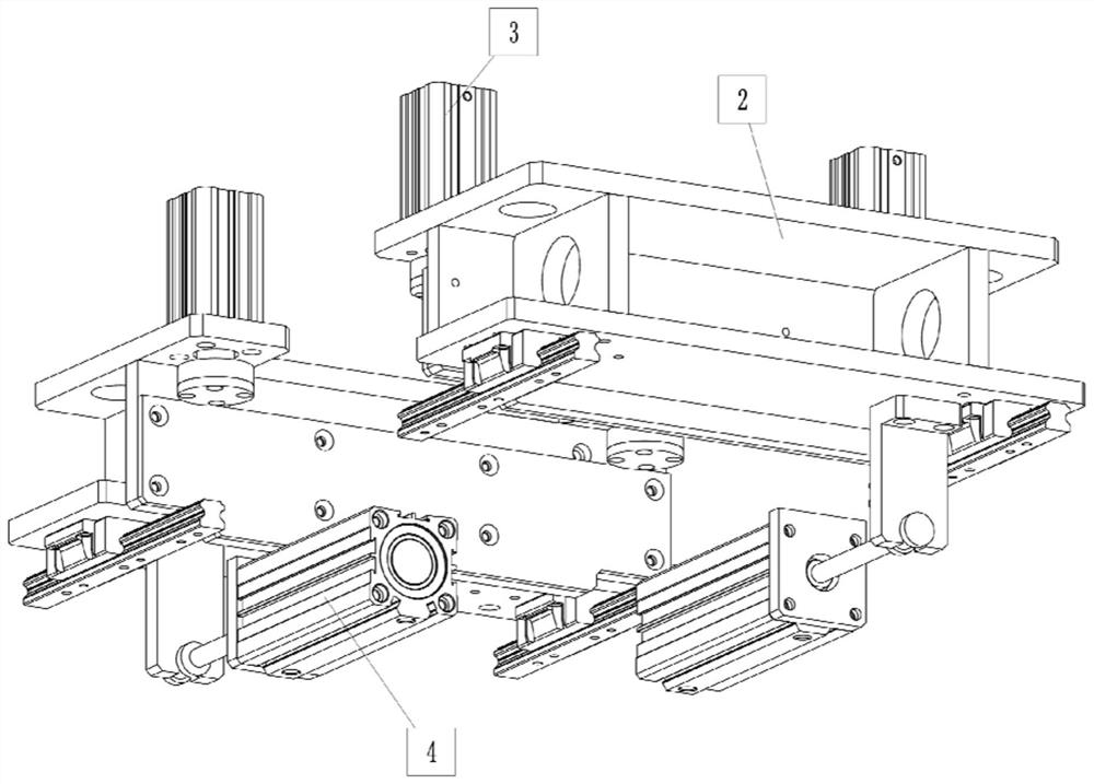
[0065] see Figure 1 to Figure 8 , an embodiment provided by the present invention: a flexible inner wall floating grinding table, including a grinding table bracket 1;

[0066] The workpiece fixing assembly is provided with two groups, and the two groups of workpiece fixing assemblies are symmetrically arranged on the top of the grinding table support 1. The workpiece fixing assembly consists of a workpiece pushing part 2, a workpiece pushing driving part 4, a workpiece positioning mechanism, The workpiece pressing assembly is formed; further, the workpiece positioning mechanism also includes: the workpiece positioning facade 101, the workpiece positioning facade 10...


PUM


Abstract

The invention discloses a flexible inner wall floating grinding table, which relates to the technical field of machining, and solves the problems that the labor intensity of workers is high, the cleaning speed is low, meanwhile, dust needs to be adsorbed through a dust suction table in the cleaning process, the adsorption effect is poor, dust diffusion is caused, and the environment is polluted. Theflexible inner wall floating grinding table comprises agrinding table support, a machining assembly and a residue collecting assembly, wherein the machining assembly is composed of a cutter lifting mechanism, a front-back sliding transposition mechanism, a cutter feeding mechanism, a cutter position adjusting mechanism, a floating machining mechanism and a dust adsorption assembly; and the residue collecting assembly is located on the lower portion of the workpiece fixing assembly and between the two groups of machining assemblies. Dust diffusion is effectively avoided, environmental pollution is reduced, residues are collected and treated in a centralized mode, floating type automatic machining of the inner wall of a workpiece is achieved, any type of residues can be well polished, labor force is liberated, the working efficiency is improved, the machining quality is improved, and meanwhile the occupied space is small.

Description

technical field [0001] The invention relates to the technical field of mechanical processing, in particular to a flexible inner wall floating grinding table. Background technique [0002] Parts need to be cut during the machining process. After the parts are cut, residues such as cutting slag and hot melt slag will remain on the cutting section, and the residue needs to be cleaned before processing. [0003] Based on the above, due to the irregularity of the residual residues in the existing pipes and tanks, it generally needs to be cleaned manually during the cleaning process. The labor intensity of the workers is high and the cleaning speed is slow. Dust is adsorbed, but the dust suction port is easy to block the line of sight, so the dust suction port needs a certain distance from the operating part, and the adsorption effect is not good, causing the dust to spread and pollute the environment; therefore, it does not meet the existing needs, and we put forward a proposal ...

Claims


Application Information

Patent Timeline
IPC IPC(8): B24B27/00B24B41/06B24B41/00B24B55/06B24B55/12
CPCB24B27/0076B24B27/0092B24B41/06B24B41/00B24B55/06B24B55/12Y02P70/10
Inventor 黄美杰张晨雷李明方磊
Owner 浙江君睿智能装备有限公司
Learn More