Multifunctional and intelligent monitoring anchor rod device

An intelligent monitoring and multi-function technology, applied in mining equipment, installation of bolts, instruments, etc., can solve the problems of easy damage, failure, and poor bolt effect of the bolt's stress point, so as to increase the life and wide adaptability. Effect

Pending Publication Date: 2022-02-01
NORTH CHINA UNIV OF WATER RESOURCES & ELECTRIC POWER +1
View PDF0 Cites 0 Cited by
  • Summary
  • Abstract
  • Description
  • Claims
  • Application Information

AI Technical Summary

Problems solved by technology

[0010] In view of the above situation, in order to overcome the defects of the prior art, the present invention provides a multi-functional and intelligent monitoring bolt device, which effectively solves the problem that the force point of the bolt in the prior art is easy to be damaged outside and eventually leads to poor bolt effect. The problems of good or even failure, and the inability to monitor rock mass deformation at different levels

Method used


Image

  • Multifunctional and intelligent monitoring anchor rod device
  • Multifunctional and intelligent monitoring anchor rod device
  • Multifunctional and intelligent monitoring anchor rod device

Examples


Embodiment 1

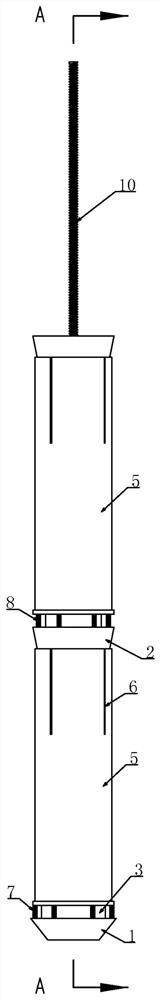
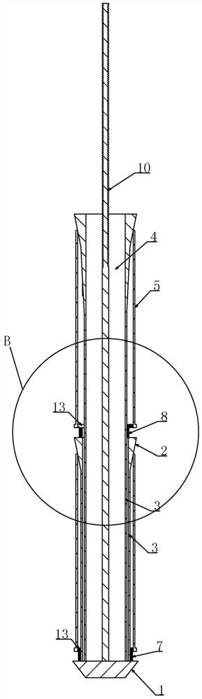
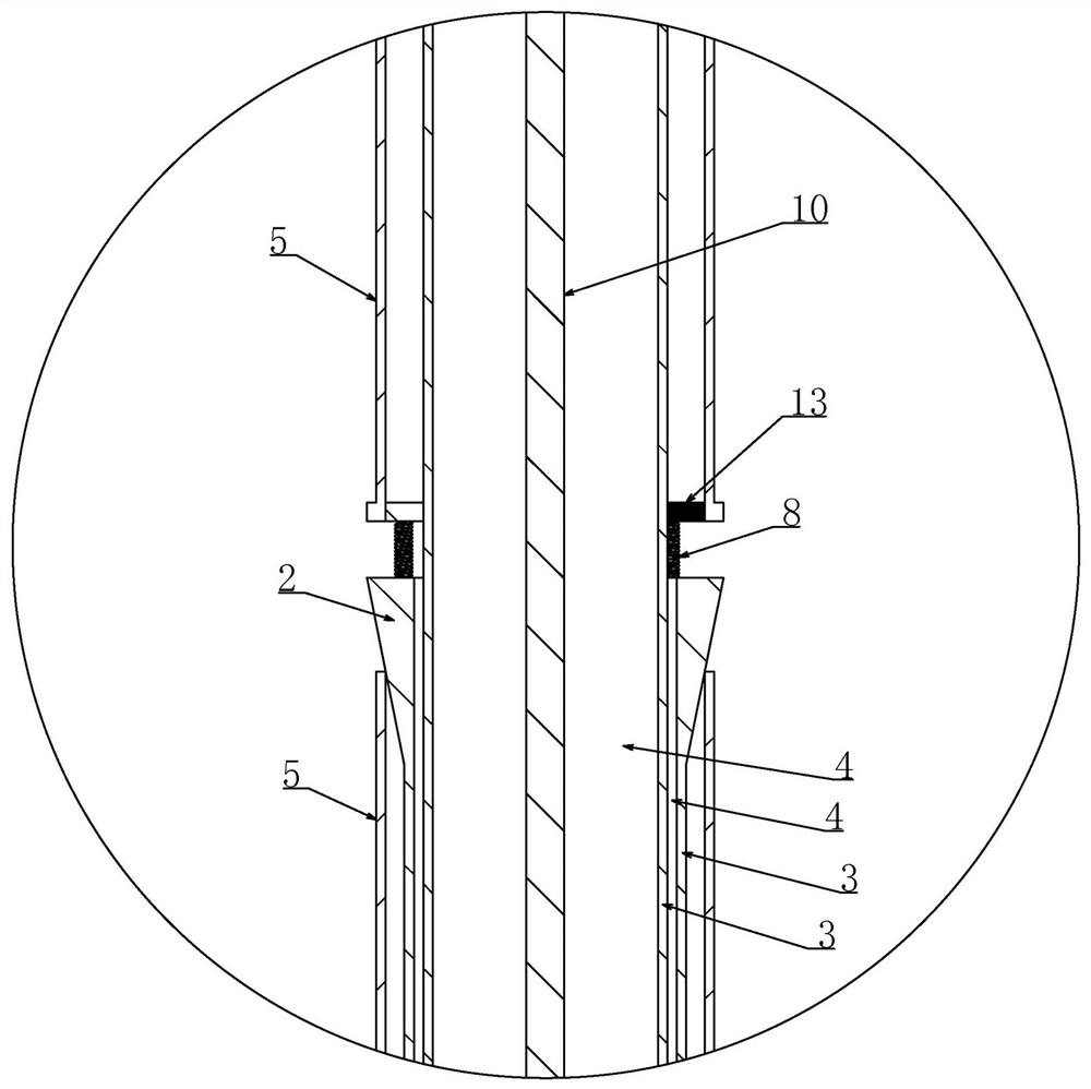
[0043] Embodiment 1, the technical solution is a multifunctional and intelligent monitoring bolt device, which includes an anchoring end 1 placed at the bottom of the anchor hole 9, and is characterized in that the anchoring end 1 is arranged axially and outwardly at intervals of several A circular frustum body 2 with an axially outwardly large and internally small, the axially inner end of the circular frustum body 2 is coaxially connected with a tension body 3, and the axially outer end of the circular frustum body 2 is provided with an axially inwardly penetrating tension body 3 through the hole 4, the tension body 3 at the innermost end in the axial direction is fixed on the anchoring end 1, and the tension body 3 at the axial outer side passes through the conical frustum body 2 and the tension body 3 adjacent to the axial inner side It passes through the hole 4 and is fixed on the anchoring end 1. The axial inner part of the circular frustum body 2 is covered with a sleeve...

Embodiment 2

[0060] Embodiment 2, on the basis of Embodiment 1, a screw 10 is fixed at the center of the anchoring end 1, and the screw 10 passes through the through hole 4 in the axially outermost conical body 2 toward the axially outward, and the A tray 11 is sheathed on the portion of the screw 10 passing through the outermost conical body 2 in the axial direction, and a nut 12 is screwed on the screw 10 on the axial outer side of the tray 11 .

[0061] A fourth through hole 28 can be opened on the tray 11 in this embodiment, and the lead wire of the displacement sensor is drawn out from the fourth through hole 28, thereby being installed on the electric control box 19 outside the anchor hole 9.

[0062] In this embodiment, a screw rod 10 is added, which is a conventional anchoring method, and one more level of protection can be set according to the situation. The screw rod 10 is fixed at the center of the anchor end 1, and then the axial outer end of the screw rod 10 extends out to the ...

Embodiment 3

[0063] Embodiment 3, on the basis of Embodiment 1, the anchoring end 1 is anchored at the axial inner end of the anchor hole 9, and the side wall of the sleeve 5 on the axial inner side of the slot 6 is anchored in the anchor hole 9, so The inner wall of the anchor hole 9 at the groove 6 is attached to the sleeve pipe 5 .

[0064] It is arranged in this way that when the side wall of the anchor hole 9 moves, the sleeve pipe 5 has a tendency to move axially outward, and the sleeve pipe 5 cooperates with the frustum 2 so that the sleeve pipe 5 has a tendency to open axially to the outside. Clinging to the side wall of the anchor hole 9, the increased expansion force prevents the side wall of the anchor hole 9 from moving outward in the axial direction. The fixation between the pipe 5 and the anchor hole 9 breaks during the movement of the rock mass, resulting in failure of the entire anchorage.


PUM


Abstract

The invention provides a multifunctional and intelligent monitoring anchor rod device. The problem that an existing anchor rod cannot monitor rock mass deformation at different levels is solved. According to the invention, an early warning effect on disasters can be achieved through monitoring of acoustic emission. The temperature of a slope and the pressure or humidity of underground water can be monitored. A plurality of circular truncated cone bodies with large outsides and small insides are arranged on the outer side of the anchoring end at intervals in the axial direction, the inner ends of the circular truncated cone bodies are coaxially connected with tension-bearing bodies, penetrating holes penetrating through the tension-bearing bodies inwards in the axial direction are formed in the axial outer ends of the circular truncated cone bodies, the tension-bearing body at the innermost end is fixed to the anchoring end, each outer tension-bearing body penetrates through the penetrating hole in the adjacent circular truncated cone body and the tension-bearing body on the axial inner side of the outer tension-bearing body to be fixed to the anchoring end, the axial inner part of each circular truncated cone body is sleeved with a sleeve with the lower end slidably arranged on the tension-bearing body in a sleeved mode, and the axial outer end of the sleeve is provided with a plurality of open grooves extending towards the axial inner side. The early warning effect on disasters is achieved through monitoring of acoustic emission. The temperature of the slope and the pressure or humidity of underground water are monitored.

Description

technical field [0001] The invention relates to a bolt, in particular to a multifunctional and intelligent monitoring bolt device. Background technique [0002] Anchor rods are widely used in slope treatment engineering, and their main function is to control surface engineering such as slopes and deep foundation pits, as well as underground chambers such as tunnels and stopes. [0003] In some surrounding rocks with relatively low grades, such as in soft rock areas, large deformations often occur in surrounding rocks, and under the action of earthquakes, large deformations often occur in some surrounding rocks. Large deformation factors also include loads, etc., and the number of bolts used as surrounding rock support structures is the largest and most widely used in work. [0004] Most of the rigid anchor rods in the prior art only directly anchor one end of the anchor rod to the bottom of the anchor hole, and then press the tray on the outer side of the slope through the ...

Claims


Application Information

Patent Timeline
IPC IPC(8): E21D20/00E21D21/02E21F17/18E02D5/74E02D33/00G08B21/10
CPCE21D20/00E21D21/02E21F17/18E02D5/74E02D33/00G08B21/10
Inventor 张兴胜陈星胡梦柯姜彤董金玉白晓璟黄子伦张军
Owner NORTH CHINA UNIV OF WATER RESOURCES & ELECTRIC POWER
Why Eureka
Try Eureka