Fixing device for catheter used in hemodialysis of child
A technology for hemodialysis and catheter fixation, applied in the direction of catheters, dialysis systems, etc., can solve the problems of space reduction, difficulty in fixing, and unsmooth air circulation, etc., to facilitate air circulation, prevent discomfort, not easy to fall and position offset effect
- Summary
- Abstract
- Description
- Claims
- Application Information
AI Technical Summary
Problems solved by technology
Method used
Image
Examples
Embodiment 1
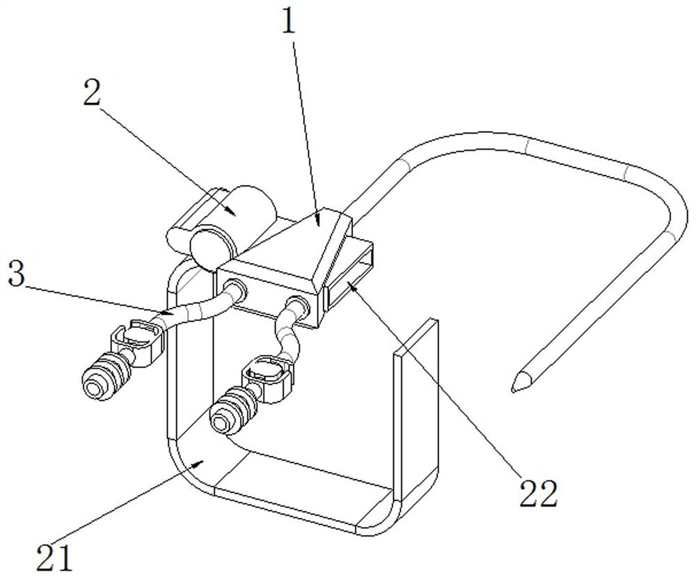
[0040] see Figure 1-5 As shown, a children's hemodialysis catheter fixing device includes a dialysis tube bifurcation block 1 and a venoarterial tube 3, and both sides of the front surface of the dialysis tube bifurcation block 1 are connected with a venoarterial tube 3;
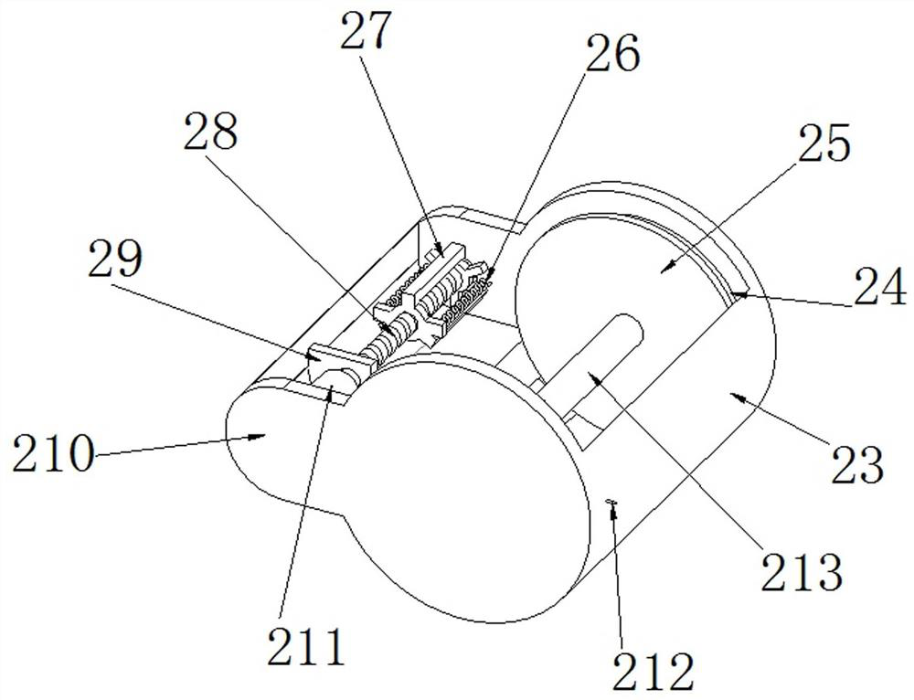
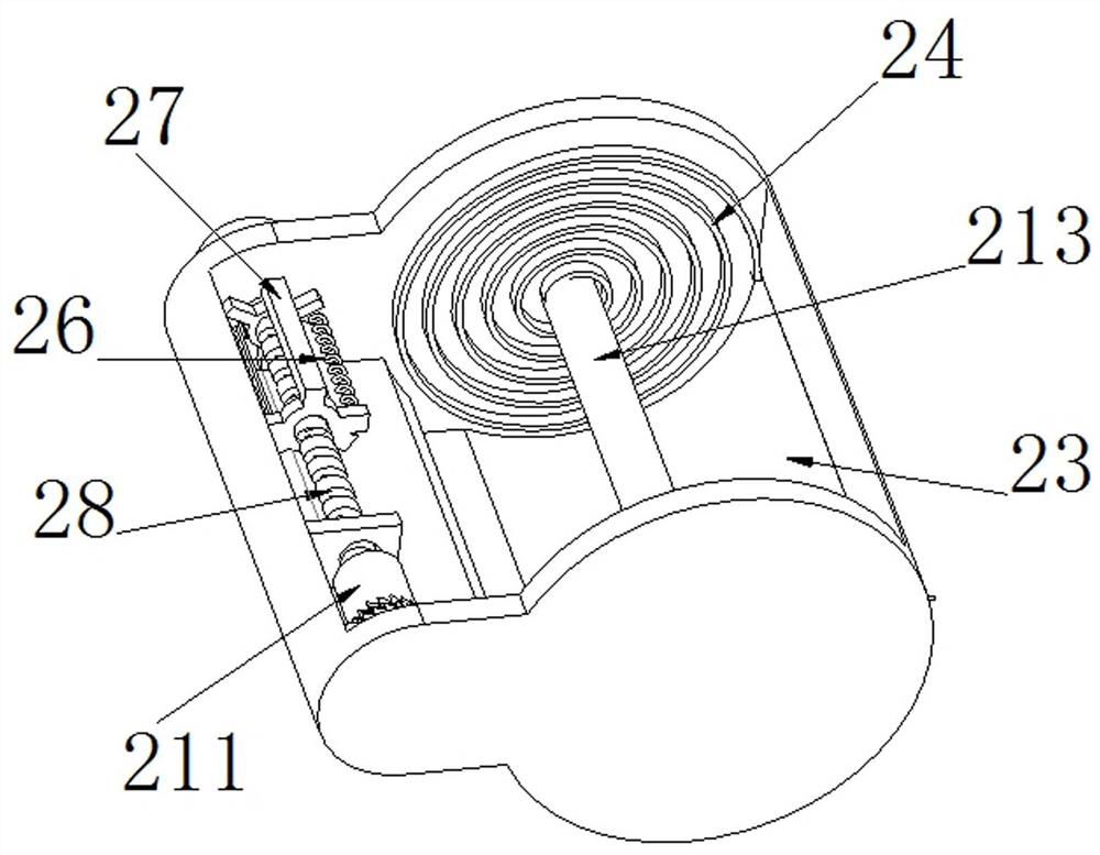
[0041] One side of the outer wall of the dialysis tube bifurcation block 1 is provided with a connecting mechanism 2, and the connecting mechanism 2 includes a storage box 23, and one side of the outer wall of the storage box 23 is connected with a rubber band 21, and the width of the rubber band 21 is smaller than the width of the storage box 23 , so that the rubber band 21 can be stored in the inside of the storage box 23 in a roll shape, and the middle position of the rear surface of the storage box 23 is rotatably connected with a support shaft 213, and one end of the rubber band 21 is connected to the outer side wall of the support shaft 213, so that The support shaft 213 can roll up the rubber band 21...
Embodiment 2
[0047] see Figure 6-7As shown, the front surface of the storage box 23 is provided with a protective mechanism 4, the protective mechanism 4 includes a second support plate 42, the four corners of the outer wall of the second support plate 42 are connected with limit rods 43, and the four limit rods 43 are movable. The activity of plate 47 is restricted, and movable plate 47 is kept level with second support plate 42 all the time in the process of moving position, and second support plate 42 center position is rotationally connected with second screw rod 44, and the outer wall of second screw rod 44 slides A movable plate 47 is connected, and the movable plate 47 slides on the second screw rod 44 through the sliding part inside. The second screw rod 44 is connected with a second gear 45 near the end of the interlocking chamber 210, and the front surface of the interlocking chamber 210 corresponds to the first gear. A screw rod 28 is connected to a first gear 46 through a conn...
Embodiment 3
[0052] see Figure 8-10 As shown, the outer wall of the second support plate 42 is provided with an anti-sweat mechanism 5, and the anti-sweat mechanism 5 includes a second connecting pipe 54, and a second telescopic hose is connected to the position corresponding to the second connecting pipe 54 on the outer wall of the second supporting plate 42. 51, the other end of the second telescopic hose 51 is connected to the movable plate 47, and can shrink and stretch following the reciprocating motion of the movable plate 47 on the second screw 44, so that the second telescopic hose 51 can stretch The outside air is transmitted to the inside of the connecting pipe 55 through the second connecting pipe 54, and flows from the inside of the connecting pipe 55 to the inside of each air bag 52. There are several air bags 52 evenly distributed on one side of the outer wall of the rubber band 21, and the outer side of the rubber band 21 The other side of the wall is connected with a conne...
PUM
 Abstract
Description
Claims
Application Information
 - R&D
- Intellectual Property
- Life Sciences
- Materials
- Tech Scout
- Unparalleled Data Quality
- Higher Quality Content
- 60% Fewer Hallucinations
Browse by: Latest US Patents, China's latest patents, Technical Efficacy Thesaurus, Application Domain, Technology Topic, Popular Technical Reports.
© 2025 PatSnap. All rights reserved.Legal|Privacy policy|Modern Slavery Act Transparency Statement|Sitemap|About US| Contact US: help@patsnap.com


