
T-beam expansion joint integral post-pouring cross beam construction method

A construction method and technology of expansion joints, applied in bridges, bridge parts, bridge construction, etc., can solve problems such as difficulty in controlling the line shape of pre-embedded steel bars, narrow space for demolding and demoulding, and large spans of poured steel bars for end-side guardrails. Solve the problem of not being damaged by fatigue and inconsistent installation of line type, facilitate the cross-span of beam-carrying vehicles, and solve the effect of crossing-span of beam-carrying vehicles

Pending Publication Date: 2022-02-08
中交二航局广西建设工程有限公司
View PDF0 Cites 0 Cited by
  • Summary
  • Abstract
  • Description
  • Claims
  • Application Information

AI Technical Summary

Problems solved by technology

[0002] The pre-embedded reinforcement of the T-beam expansion joint of an expressway is designed to be pre-embedded in the beam end of the main beam in advance. Specifically, the T-beam is designed to be at the end of the expansion joint, and N1 door-type reinforcement needs to be embedded, and the top surface of the steel bar is higher than the T-beam beam. The surface is 10cm, which affects the traffic of beam transport vehicles and concrete transport vehicles on the bridge deck. During the construction process, it needs to be laid flat, and the vehicles pass through repeated rolling. Later, it will be pried up and connected with the post-tied steel bars. The pre-embedded threaded steel bars are repeated on the beams. Bending, prone to fatigue fractures, easily lead to bending and breaking of threaded steel bars, seriously affecting the quality and service life of expansion joints during the operation period; in actual construction, the line shape of pre-embedded steel bars in expansion joints is difficult to control, and there are problems of uneven installation , therefore, increase the maintenance cost of expansion joints during the operation period
[0003] At the same time, due to the unitary multi-directional displacement expansion joints, the length of the longitudinal beam exceeds the distance from the end diaphragm to the beam end, and the main reinforcement of the end diaphragm is close to the top surface of the beam slab, so the top of the end diaphragm cannot be poured at the same time. The formwork for the end closure needs to be rebuilt, and the joint formwork at the end is prone to grout leakage; the expansion joint is wide and exceeds the space of the end diaphragm, resulting in a large span of reinforcement poured on the guardrail at the end of the expansion joint, and the concrete is prone to cracking after pouring; After the construction of the T-beam expansion joint is completed, it is connected with the post-cast beam as a whole, and the overall installation is carried out at the expansion joint. There is a problem that the pouring and demoulding space is narrow and difficult to reinforce.

Method used


Image

  • T-beam expansion joint integral post-pouring cross beam construction method
  • T-beam expansion joint integral post-pouring cross beam construction method
  • T-beam expansion joint integral post-pouring cross beam construction method

Examples


Embodiment 1

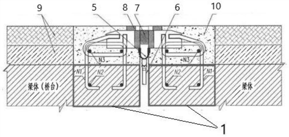
[0033] See figure 1 After pouring the whole beam T joints Example of the present embodiment provides a method of construction beams,

[0034] 1) In the additional slot of the main beam end joints 1;

[0035] 80 is a comb-type expansion joint plate joints, the size of a notch 35cm × 20cm, the size of the original reserve slots deepen;

[0036] 2) not embedded joints when erect steel prefabricated beams T, T the steel beams to rest upon the original design and construction, the T beam, first erect steel joints for construction design drawing, and then pouring slot joints 1 concrete;

[0037] 3) After the casting joints by cross beams T reservation steel top plate formed integrally with the beam connected to T beam construction is completed.

[0038] In this embodiment, the end joints in a predetermined slot in advance, without hanger bars embedded joints, so that the expansion joint reinforcement strong fatigue fracture, and mounting reinforcement linear manner consistent with the c...

Embodiment 2

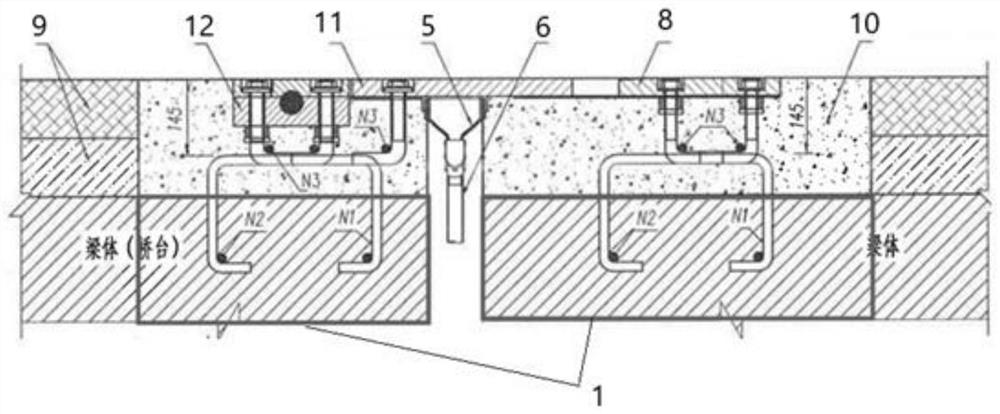
[0041] See figure 2 After pouring the whole beam T joints Example of the present embodiment provides a method of construction beams,

[0042] 1) In the additional slot of the main beam end joints 1;

[0043] Multi-cell expansion joints 160 joints to the displacement, the size of the slot 1 is 66cm × 20cm, the size of the original reserve slots deepen;

[0044] 2) not embedded joints when erect steel prefabricated beams T, T the steel beams to rest upon the original design and construction, the T beam, first erect steel joints for construction design drawing, and then pouring slot joints concrete;

[0045] 3) After the casting joints by cross beams T reservation steel top plate formed integrally with the beam connected to T beam construction is completed.

[0046] In this embodiment, the end joints in a predetermined slot in advance, without hanger bars embedded joints, so that the expansion joint reinforcement strong fatigue fracture, and mounting reinforcement linear manner consi...

Embodiment 3

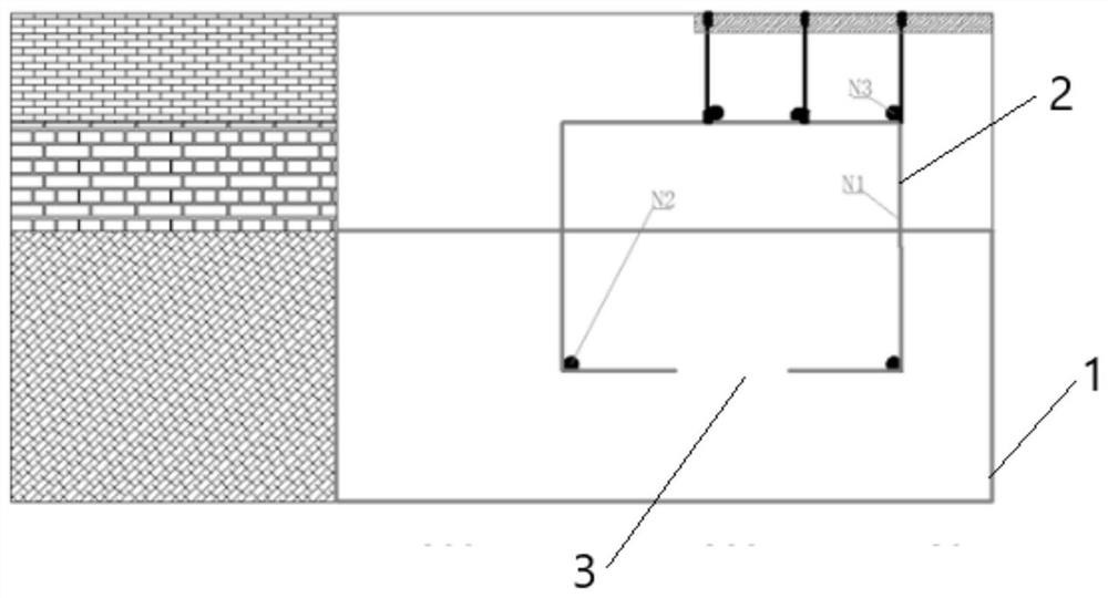
[0049] See image 3 On the basis of Example 1 and Example 2, at the T beam preformed, the end mold steel plate 2 with the reserved hole 3 is provided on the main beam body, and the end mold steel sheet 2 is accepted by the added slot 1. Place.

[0050] In the case, the position of the reserved hole 3 is determined according to the position of the steel bar on the main beam body, and the molded sheet is applied between the remaining gaps, reaches the slurry effect.


PUM


Abstract

The invention belongs to the technical field of bridge construction, and relates to a T-beam expansion joint integral post-pouring cross beam construction method which comprises the following steps that: (1), a T-beam main beam is prefabricated, and a notch is additionally arranged at an expansion joint end of the T-beam main beam according to an expansion joint structure on the main beam; (2), expansion joint erecting steel bar construction is conducted according to the design, and concrete is poured into the notch; and (3), the T-beam main beam is integrally connected with the expansion joint post-cast cross beam through reserved steel bars, T-beam construction is completed, a T-beam expansion joint is a comb plate type expansion joint, the size of the notch is 35 cm*20 cm, the T-beam expansion joint is a unit type multidirectional displacement expansion joint, and the size of the notch is 66 cm*20 cm. According to the method, the notch is additionally formed in the expansion joint end of the main beam, expansion joint erecting steel bar and other steel bar construction is conducted firstly, and then the expansion joint notch section is integrally poured, it is guaranteed that the expansion joint steel bars are resistant to fatigue damage and consistent in linear installation, construction is easy to operate and control, and the maintenance cost is reduced.

Description

Technical field [0001] The present invention belongs to the technical field of bridge construction, the construction method of pouring after the entire beam is directed to a T beam joints. Background technique [0002] Beam expansion joint on a motorway T embedded reinforcement embedded in advance in the design of the beam end of the main beam, in particular, the design beam expansion joint end T, N1 door for an embedded reinforcement, steel girder and the top surface of comparing T face 10cm, bridge girder vehicle impact concrete trucks and other traffic, need to finish the construction process flat, vehicle traffic was repeatedly passed, then pry post connected to the rear tie steel, embedded in the beam panel repeatedly rebar bending, prone to fatigue fracture phenomenon, easily lead to bending rebar break, seriously affecting the operation of the expansion joints using quality and service life; the actual construction of embedded steel linear expansion joints are difficult to...

Claims


Application Information

Patent Timeline
Patent Type & Authority Applications(China)
IPC IPC(8): E01D21/00E01D19/06E01D2/00
CPCE01D21/00E01D19/06E01D2/00
Inventor 黄海波张帆张小容邹为宇杨博闻冯雁麟徐业锦
Owner 中交二航局广西建设工程有限公司
Learn More