
A Curve Fitting Method Based on Velocity Planning

A technology of curve fitting and speed planning, which is applied in the direction of program control, instrument, electrical program control, etc., can solve the problems of discrete straight lines or arc segments, increasing the processing capacity and calculation burden of the numerical control system, etc., to achieve speed planning and The interpolation calculation is simple, meets the real-time requirements, and reduces the calculation burden

Active Publication Date: 2022-06-21
TIANJIN UNIVERSITY OF TECHNOLOGY
View PDF5 Cites 0 Cited by
  • Summary
  • Abstract
  • Description
  • Claims
  • Application Information

AI Technical Summary

Problems solved by technology

[0005] The purpose of the present invention is to solve the problem that the existing numerical control system requires a large number of discrete straight lines or arc segments when performing speed planning and interpolation processing on curves, which increases the processing capacity and calculation burden of the numerical control system, and proposes a method based on Curve Fitting Method for Velocity Planning

Method used


Image

  • A Curve Fitting Method Based on Velocity Planning
  • A Curve Fitting Method Based on Velocity Planning
  • A Curve Fitting Method Based on Velocity Planning

Examples


specific Embodiment approach 1

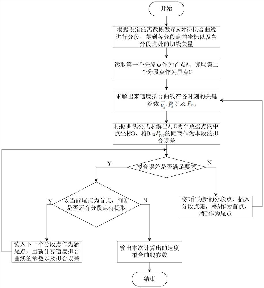
[0056] Specific implementation mode 1. Combination figure 1 and Image 6 This embodiment will be described. A curve fitting method based on speed planning described in this embodiment, the method specifically includes the following steps:

[0057] Step 1. Input the parameters of the curve to be fitted, and segment the curve to be fitted according to the set number of discrete segments N, to obtain the coordinates of each segmented point and the tangent vector at each segmented point;

[0058] According to the input parameters, the curve to be fitted can be generated, and then the curve to be fitted can be segmented according to the set number of discrete segments N, and then the midpoint coordinates of each segment for subsequent comparison can be obtained;

[0059] Step 2. Read in the first segment point and the second segment point, take the first segment point as the first point and record it as point A(x A ,y A ,z A ), take the second segment point as the end point an...

specific Embodiment approach 2

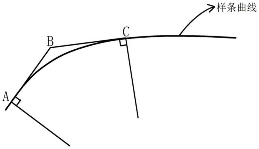
[0068] Specific embodiment 2: The difference between this embodiment and specific embodiment 1 is that the initial velocity v at point A is calculated according to the length of the straight line segment AB A , and then according to v A Calculate the acceleration a on the straight line segment AB AB ; The specific process is:

[0069]

[0070] Among them, s AB is the length of straight line segment AB,

[0071]

[0072] Other steps and parameters are the same as those in Embodiment 1.

specific Embodiment approach 3

[0073] Specific embodiment 3: The difference between this embodiment and specific embodiment 1 or 2 is that the velocity v at point C is calculated according to the length of straight line segment BC C , and then according to v C Calculate the acceleration a on the straight line segment BC BC ; The specific process is:

[0074]

[0075] Among them, s BC is the length of straight line segment BC,

[0076]

[0077] Other steps and parameters are the same as those in Embodiment 1 or Embodiment 2.


PUM


Abstract

The invention discloses a curve fitting method based on speed planning, which belongs to the technical field of speed planning and interpolation of numerical control system. The invention solves the problem that the existing numerical control system requires many discrete straight lines or arc segments when performing speed planning and interpolation processing on curves, which increases the processing capacity and calculation burden of the numerical control system. The position coordinate obtained by the curve fitting method of the present invention is a simple quadratic equation, and the tangent vector direction is only a first-order equation, so that the subsequent speed planning and interpolation calculation are relatively simple. Moreover, the present invention can use fewer segments to meet the fitting accuracy, and because the present invention requires less discrete segments, the processing load of the numerical control system is reduced, and the calculation burden is lightened. Since the method of the invention reduces the processing capacity of the numerical control system and lightens the calculation burden, it can well meet the real-time requirements of subsequent speed planning and interpolation processing. The invention can be applied to the speed planning and interpolation processing of the numerical control system.

Description

technical field [0001] The invention belongs to the technical field of speed planning and interpolation of a numerical control system, and in particular relates to a curve fitting method based on speed planning. Background technique [0002] With the increase of modeling complexity, many product designs adopt curve and surface modeling, and the main curve forms used are spline curves, such as nurbs curve (non-uniform rational B-spline curve), B-spline, Bezier curve, etc. First, the CAM software is used to plan the tool path path, and then after post-processing, it is converted into a G code that can be recognized by the CNC system for processing. The CAM software often uses two methods for the processing of the curve. One is to directly output the curve. Value points, control points, weights and other information are input to the CNC system, and the CNC system performs speed planning and interpolation of the curve. The other is to discretize the curve into straight line seg...

Claims


Application Information

Patent Timeline
Patent Type & Authority Patents(China)
IPC IPC(8): G05B19/4103
CPCG05B19/4103G05B2219/34117
Inventor 刘清建刘振忠刘志刚李政张昆鹏
Owner TIANJIN UNIVERSITY OF TECHNOLOGY
Learn More