High-voltage ceramic vacuum relay
A ceramic vacuum and high-voltage technology, applied in high-voltage air circuit breakers, high-voltage/high-current switches, circuits, etc., can solve problems such as surface oxidation of conductive columns, achieve long conductivity, high practicability, and avoid surface oxidation.
- Summary
- Abstract
- Description
- Claims
- Application Information
AI Technical Summary
Problems solved by technology
Method used
Image
Examples
Embodiment 1
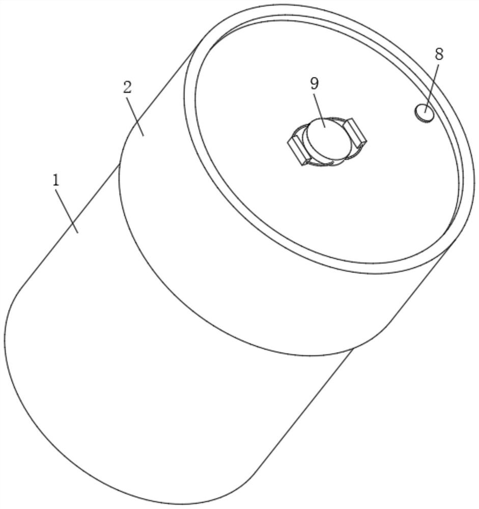
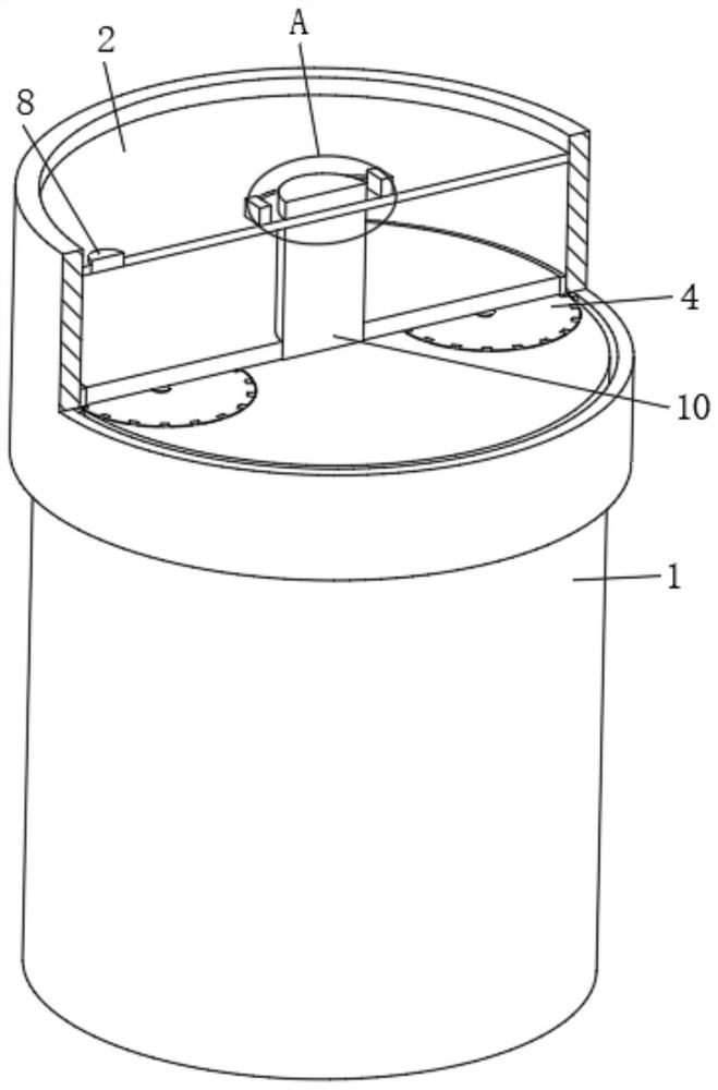
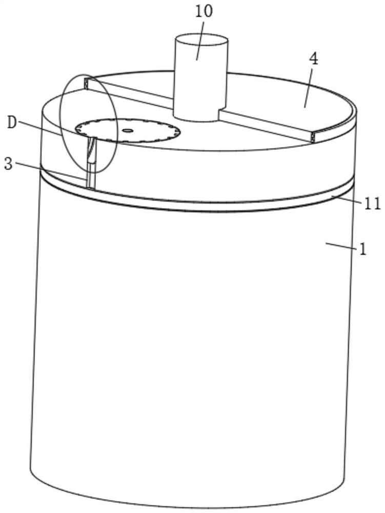
[0031] see Figure 1 to Figure 4 , Figure 8 and Figure 10 , this embodiment provides a high-voltage ceramic vacuum relay: including a housing 1 and an energization mechanism arranged in the housing 1. The energization mechanism is a mature technology in the existing relay, and will not be described in detail here. It can be found in the authorized announcement number: Obtained in the patent document of CN213070996U, during use, the shell 1 is fixed at the position to be installed, and the function of the high-voltage ceramic vacuum relay can be completed by cooperating with the internal energizing mechanism; the upper surface of the shell 1 is fixedly installed with a conductive column 10 connected to the energizing mechanism , that is, electricity is passed between the conductive column 10 and the energization mechanism.
[0032] The upper surface of the casing 1 is symmetrically provided with two L-shaped placement grooves 3, the L-shaped placement grooves 3 are set upsi...
Embodiment 2
[0037] see Figure 1 to Figure 6 , Figure 8 to Figure 10, on the basis of Embodiment 1, the rotating assembly 4 includes a runner 401 that is rotatably connected to the L-shaped placement groove 3, and the two L-shaped placement grooves 3 correspond to two runners 401, and the outer surfaces of the two runners 401 are opened There are several guide grooves 402 with inclined design, and several guide grooves 402 are arranged in a circular array along the outer surface of the runner 401. The upper end of each guide groove 402 corresponds to the lower end of the previous guide groove 402, and each guide groove The lower ends of the grooves 402 are all corresponding to the upper ends of the next guide groove 402; the insides of the two runners 401 are all threaded with connecting rods 403 which are slidingly fitted with the casing 1, and the tops of the two connecting rods 403 are all connected with the push plate 405. The bottom is rotationally connected, and the two connecting...
Embodiment 3
[0041] see Figure 1 to Figure 10 , on the basis of the second embodiment, the outer surface of the housing 1 is provided with an annular groove in the middle of the L-shaped placement groove 3 and the external thread, and the inner part of the annular groove is provided with a sealing ring matching the size of the annular groove 11. The sealing ring 11 is sleeved behind the annular groove and completely hidden in the annular groove, that is, the opening size of the sealing ring 11 is smaller than the diameter of the casing 1 at this time, and the protective cover 2 will not collide with the sealing ring 11 when it descends. Frictional contact.
[0042] The inside of the shell 1 is provided with a cavity (not shown) connected to the annular groove, and the cavity is provided with a moving assembly 5 that is movably matched with the bottom of the connecting rod 403 and movably fitted with the sealing ring 11. It is used to adjust the opening degree of the sealing ring 11. The...
PUM
 Abstract
Description
Claims
Application Information
 - R&D
- Intellectual Property
- Life Sciences
- Materials
- Tech Scout
- Unparalleled Data Quality
- Higher Quality Content
- 60% Fewer Hallucinations
Browse by: Latest US Patents, China's latest patents, Technical Efficacy Thesaurus, Application Domain, Technology Topic, Popular Technical Reports.
© 2025 PatSnap. All rights reserved.Legal|Privacy policy|Modern Slavery Act Transparency Statement|Sitemap|About US| Contact US: help@patsnap.com


