
IBC solar cell structure of TOPCon back passivation contact structure and preparation method thereof

A solar cell and contact structure technology, which is applied in the field of solar cells, can solve the problems of unreasonable positive and negative electrode graphic design, large composite metal contact area, and difficult to distinguish, and achieve the effects of ensuring good contact, optimizing growth mode, and being easy to distinguish

Pending Publication Date: 2022-02-08
欧文凯
View PDF0 Cites 0 Cited by
  • Summary
  • Abstract
  • Description
  • Claims
  • Application Information

AI Technical Summary

Problems solved by technology

However, the existing IBC battery manufacturing technology still has problems such as high cost, large composite metal contact area, and unreasonable graphic design of positive and negative electrodes, which affects the difficulty of distinguishing components during welding.

Method used


Image

  • IBC solar cell structure of TOPCon back passivation contact structure and preparation method thereof
  • IBC solar cell structure of TOPCon back passivation contact structure and preparation method thereof
  • IBC solar cell structure of TOPCon back passivation contact structure and preparation method thereof

Examples


Embodiment

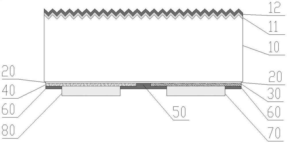
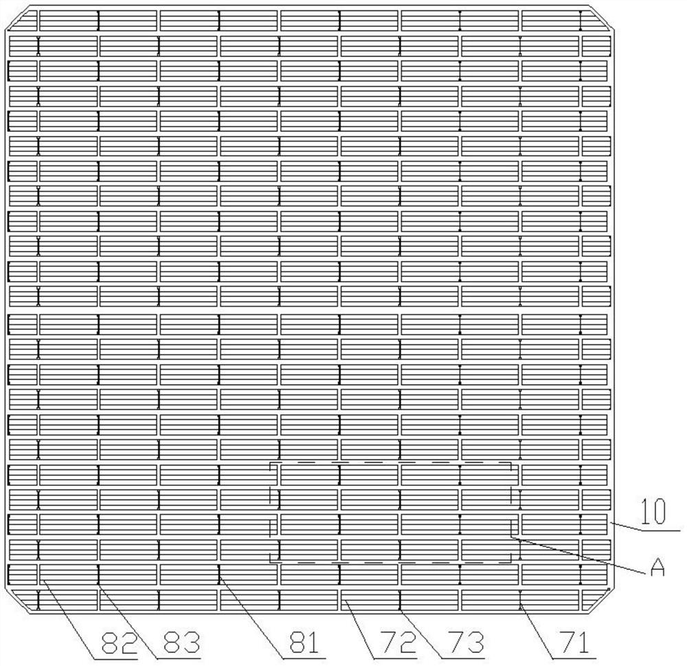
[0046] Such as Figure 1-4 Shown: an IBC solar cell structure with a TOPCon rear passivation contact structure, mainly comprising a crystalline silicon substrate, the front surface of the crystalline silicon substrate 10 includes a front doped layer 11 and a front passivation layer 12 from the inside to the outside, the crystal The back surface of the silicon substrate includes, from the inside to the outside, tunnel oxide layers 20, alternately arranged n+ doped amorphous silicon layers 30, p+ doped amorphous silicon layers 40, laser grooved regions 50, and a back surface passivation layer. 60. Negative electrode 70 / positive electrode 80.

[0047] Wherein, the crystalline silicon substrate 10 is any one of N-type single crystal silicon or P-type single crystal silicon. In this embodiment, the crystalline silicon substrate 10 is N-type single crystal silicon; the front surface of the crystalline silicon substrate 10 is made of Suede with polished back surface.

[0048] The t...


PUM

PropertyMeasurementUnit
Widthaaaaaaaaaa
Thicknessaaaaaaaaaa
Square resistanceaaaaaaaaaa

Abstract

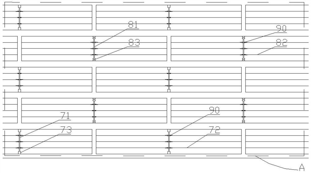
The invention provides an IBC solar cell structure of a TOPCon back passivation contact structure and a preparation method thereof. The IBC solar cell structure comprises a crystalline silicon substrate, and the front surface of the crystalline silicon substrate comprises a front doping layer and a front passivation layer from inside to outside. The back surface of the crystalline silicon substrate comprises a tunneling oxide layer, n + doped amorphous silicon layers / p + doped amorphous silicon layers which are alternately arranged, a laser slotting region, a back passivation layer and a negative electrode / positive electrode from inside to outside. According to the invention, the cell structure combining a TOPCon back contact passivation mode and a heterojunction mode is adopted, the growth mode of doped amorphous silicon is optimized, so that the passivation capability and contact capability of the solar cell are improved under the condition that the characteristic of high short-circuit current of IBC is kept, and the manufacturing cost is effectively reduced at the same time; and secondly, by optimizing the metal positive electrode and the metal negative electrode, narrowing the width of the main grid line and increasing pad points, the consumption of slurry can be reduced, and the positive pad and the negative pad are distinguished according to different patterns, so that distinguishing during assembly welding is facilitated, and the probability of assembly welding errors is reduced.

Description

technical field [0001] The invention relates to the field of solar cells, in particular to an IBC solar cell structure with a TOPCon back passivation contact structure and a preparation method thereof. Background technique [0002] In recent years, with the continuous improvement of energy demand, the depletion of traditional fossil fuel energy and the enhancement of people's awareness of environmental protection, the development of clean, environmentally friendly and renewable energy has become a top priority for human development. Solar energy is a clean and renewable energy. Energy is inexhaustible and inexhaustible. Therefore, the development and utilization of clean, environmentally friendly and renewable new energy represented by solar energy will become one of the most promising energy sources. [0003] For crystalline silicon solar cells, especially IBC cells, the characteristic is that the front of the cell has no electrodes, and the positive and negative electrode...

Claims


Application Information

Patent Timeline
IPC IPC(8): H01L31/0224H01L31/0216H01L31/068H01L31/20
CPCH01L31/0682H01L31/202H01L31/022458H01L31/02167Y02E10/547Y02P70/50
Inventor 欧文凯李含朋向亮睿
Owner 欧文凯
Learn More