Machining process for air flow channel of diffuser and numerical control milling clamp

A technology of air flow channel and processing technology, which is applied in the direction of manufacturing tools, metal processing equipment, metal processing machinery parts, etc., and can solve problems such as changes, the precise size of the blade shape cannot be guaranteed, and the transfer of axial blades is smooth, etc.

Active Publication Date: 2022-02-11
HUNAN SOUTH GENERAL AVIATION ENGINE CO LTD
View PDF6 Cites 0 Cited by
  • Summary
  • Abstract
  • Description
  • Claims
  • Application Information

AI Technical Summary

Problems solved by technology

[0005] 1. It is impossible to realize the smooth connection between the root of the radial blade and the axial blade and the hub, and the surface roughness cannot be guaranteed to be qualified; the three-axis digital milling process for radial blades and the four-axis digital milling process for axial blades need to be smooth with the hub Transfer, but in the actual processing process, due to the inconsistent clamping state of the process and the stress deformation of the parts, the roots of the radial blades and axial b...

Method used


Image

  • Machining process for air flow channel of diffuser and numerical control milling clamp
  • Machining process for air flow channel of diffuser and numerical control milling clamp
  • Machining process for air flow channel of diffuser and numerical control milling clamp

Examples


Embodiment Construction

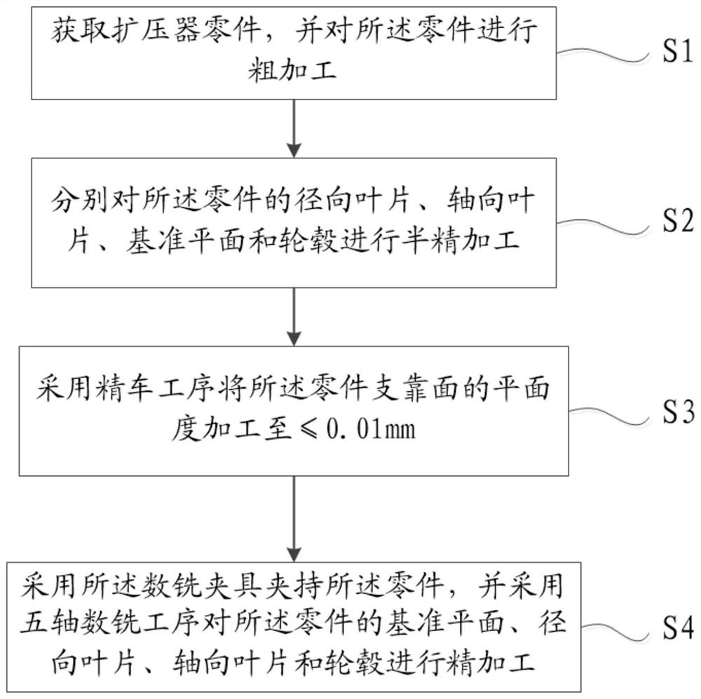
[0054] The core of the present invention is to provide a processing technology of the diffuser air channel and a digital milling fixture, which are used to eliminate stress deformation and compaction deformation generated during the processing of parts, and improve the qualified rate.

[0055] In order to enable those skilled in the art to better understand the solution of the present invention, the present invention will be further described in detail below in conjunction with the accompanying drawings and specific embodiments.

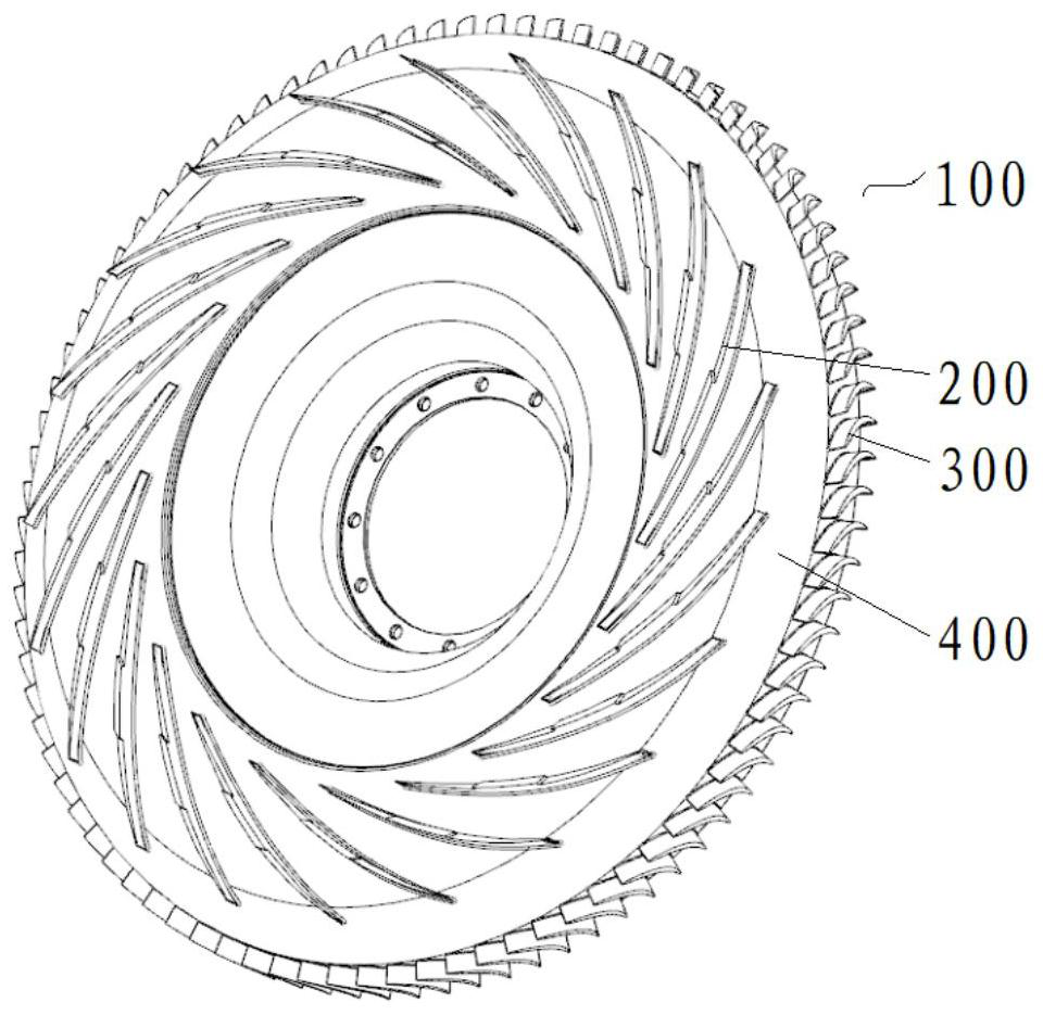
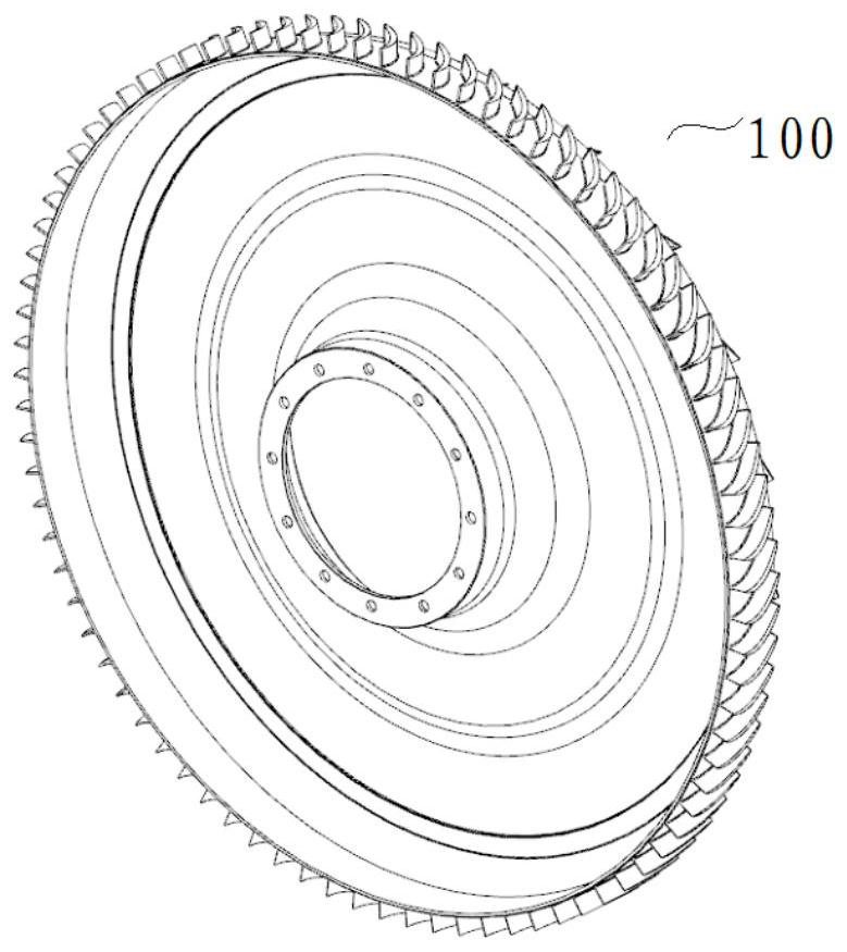
[0056] Please refer to figure 1 as well as Figure 4 to Figure 8 , figure 1 A flow chart of the processing technology of the diffuser air channel provided by the present invention; Figure 4 It is a schematic diagram of the finishing process in the processing technology of the diffuser air channel provided by the present invention; Figure 5 It is a schematic diagram of the five-axis digital milling process in the processing technology of the air ...


PUM


Abstract

The invention discloses a machining process for an air flow channel of a diffuser and a numerical control milling clamp. The machining process comprises the steps that a diffuser part is obtained, and rough machining is conducted; semi-finishing are carried out on radial blades, axial blades, a reference plane and a hub of the part respectively; the planeness of the supporting face on the inner side of the end face of the part is machined to be smaller than or equal to 0.015 mm through the finish turning procedure; a numerical milling clamp is adopted to clamp the part, and a five-axis numerical milling procedure is adopted to carry out finish machining on the reference plane, the radial blades, the axial blades and the hub of the part. According to the machining process, the allowance is removed in the rough machining stage and the semi-finish machining stage, and stress deformation generated in the rough machining stage is eliminated; in the finish machining stage, a numerical turning procedure is adopted for preparing for clamping of a subsequent five-axis numerical milling procedure, pressing deformation is avoided, then the radial blades, the axial blades and a switching arc are combined in one five-axis numerical milling procedure, one-time tool clamping is carried out, size machining is completed, and it is guaranteed that the blade profile size and the surface roughness of the air flow channel meet the requirements.

Description

technical field [0001] The invention relates to the field of diffuser processing, in particular to a processing technology and a digital milling fixture for an air channel of a diffuser. Background technique [0002] For aeroengine diffuser parts, such as figure 1 As shown, due to its thin wall thickness, it is an ultra-thin-walled annular part with irregular shape and poor structural rigidity; the material has poor machinability, the cutting force of the tool is large, and the part is easily deformed by external force; the air flow path of the part is composed of radial blades, axial Composed of blades and hubs, it has high requirements for dimensional accuracy such as blade surface profile and surface roughness. [0003] In the prior art, as shown in Figure 2 to Figure 3, in order to realize the processing of the air channel of the diffuser, the process flow is divided into two stages of rough machining and finish machining, and the rough machining process is arranged in ...

Claims


Application Information

Patent Timeline
IPC IPC(8): B23P15/00B23C9/00B23Q3/06
CPCB23P15/00B23C9/00B23Q3/06
Inventor 李彬邵聪周钉宋光荣刘安洪
Owner HUNAN SOUTH GENERAL AVIATION ENGINE CO LTD
Why Eureka
Try Eureka