
Large-scale and continuous waste organic matter energy conversion device

A conversion device, continuous technology, applied in the preparation of liquid hydrocarbon mixture, petroleum industry, processing of hydrocarbon oil, etc., can solve the problems of low production efficiency, inability to carry out high temperature feeding, inability to carry out high temperature slag discharge, etc., to achieve effective Utilize the effect of non-condensable gas

Pending Publication Date: 2022-02-11
广西海鸥能源装备有限公司
View PDF6 Cites 0 Cited by
  • Summary
  • Abstract
  • Description
  • Claims
  • Application Information

AI Technical Summary

Problems solved by technology

[0003] In the prior art, most of them are small-scale single-processing equipment, which usually use small-scale reactors to produce one kettle after another. It is difficult to achieve joint production of multiple kettles, and neither high-temperature feeding nor high-temperature slag discharge is possible. A large-scale continuous carburetion device for waste organic matter has been put into use
After some equipment has been improved, the problems of continuous feeding and high-temperature slag discharge have been solved. However, the material cannot be fed within one hour before slag discharge. During this hour, the oil in the slag is completely melted, and then the Refeeding can only be done after the slag is discharged, which is not continuous feeding in an absolute sense, and the production scale is small, and the production efficiency is not high

Method used


Image

  • Large-scale and continuous waste organic matter energy conversion device
  • Large-scale and continuous waste organic matter energy conversion device
  • Large-scale and continuous waste organic matter energy conversion device

Examples


Embodiment Construction

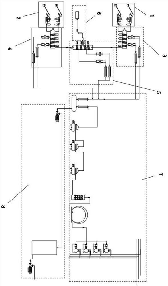
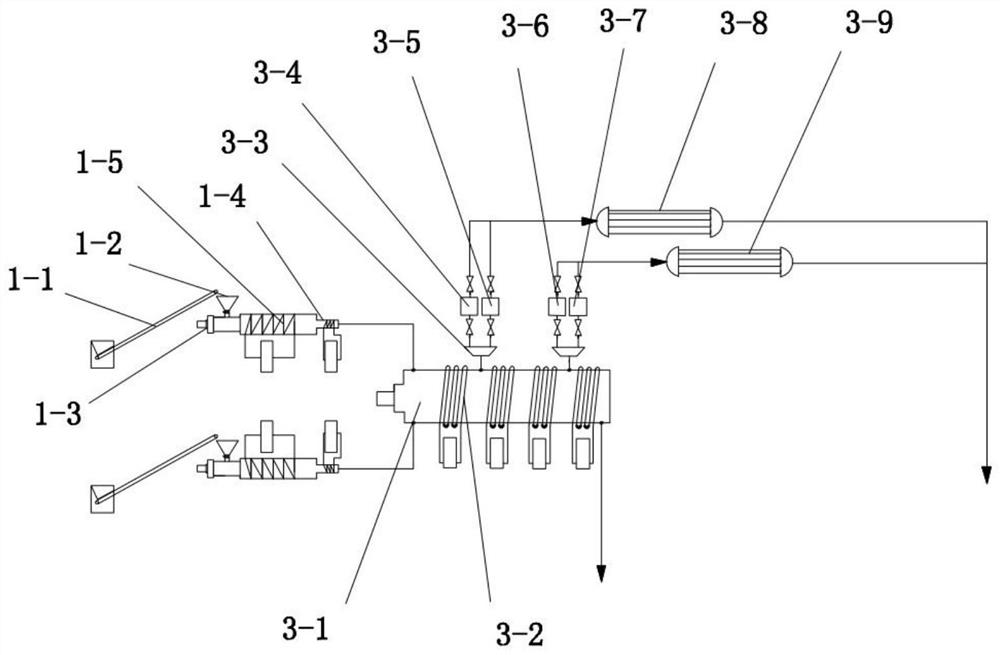
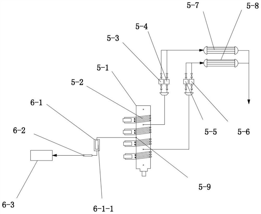
[0025] see Figure 1-Figure 6As shown, the technical solution adopted in this specific embodiment is: it includes a first conveying mechanism 1, a second conveying mechanism 2, a first reaction mechanism 3, a second reaction mechanism 4, a slag discharge mechanism 5, a slag storage mechanism 6, a gas The processing mechanism 7, the oil processing mechanism 8, the first conveying mechanism 1 and the second conveying mechanism 2 have the same structure, the first reaction mechanism 3 and the second reaction mechanism 4 have the same structure, and the first conveying mechanism 1 is connected to the first reaction mechanism 3 through the pipeline. The second conveying mechanism 2 is connected with the second reaction mechanism 4 through the pipeline, the first reaction mechanism 3 and the second reaction mechanism 4 are connected with the slag discharge mechanism 5 through the pipeline, and the slag discharge mechanism 5 is connected with the slag storage mechanism through the pip...


PUM

PropertyMeasurementUnit
diameteraaaaaaaaaa
thicknessaaaaaaaaaa
diameteraaaaaaaaaa

Abstract

The invention discloses a large-scale and continuous waste organic matter energy conversion device, and relates to the technical field of petrochemical equipment. First conveying mechanisms are connected with a first reaction mechanism through pipelines, a second conveying mechanism is connected with a second reaction mechanism through a pipeline, the first reaction mechanism and the second reaction mechanism are connected with a slag discharging mechanism through pipelines, and the slag discharging mechanism is connected with a slag storage mechanism through a pipeline. The first reaction mechanism, the second reaction mechanism and the slag discharging mechanism are all connected with a gas treatment mechanism through pipelines, and two groups of the first conveying mechanisms are arranged. The purposes of continuous feeding, continuous slag discharging and effective utilization of non-condensable gas are achieved, meanwhile, the energy-saving purpose is achieved by fully utilizing heat energy of the non-condensable gas, the whole system works under sealed anaerobic micro-negative pressure, the non-condensable gas is collected, stored and subjected to high-temperature combustion work of a gas engine, dioxins in the non-condensable gas are thoroughly decomposed, tail gas of a gas engine is free of dioxins any more, and harmful gas and dust in the tail gas of the gas engine are effectively controlled.

Description

technical field [0001] The invention relates to a large-scale, continuous waste organic matter energy conversion device, and relates to the technical field of carburetion equipment. Background technique [0002] In the production process of modern enterprises, some waste organic matter is often produced. If these waste organic matter is not properly treated, it will cause environmental pollution. In addition, the treated waste organic matter can also be converted into energy for reuse. [0003] In the prior art, most of them are small-scale single-processing equipment, usually using small-scale reactors, one kettle after another for production, it is difficult to achieve multi-pot co-production, neither high-temperature feeding nor high-temperature slag discharge is possible. A large-scale continuous carburetion device for waste organic matter has been put into use. After some equipment has been improved, the problems of continuous feeding and high-temperature slagging have...

Claims


Application Information

Patent Timeline
Patent Type & Authority Applications(China)
IPC IPC(8): C10G1/02C10G1/00
CPCC10G1/002C10G1/02C10G2300/1003
Inventor 覃坚涧王忠
Owner 广西海鸥能源装备有限公司
Learn More