Protective layer grounding fault detection method, positioning method, detection system and positioning system

A ground fault and detection method technology, which is used in electrical measurement, measurement device, short-circuit test, etc., can solve the problem of low accuracy, and achieve the effect of reducing labor intensity, simple calculation method, and reducing investigation time.

Pending Publication Date: 2022-02-11
徐忠林 +7
View PDF7 Cites 3 Cited by
  • Summary
  • Abstract
  • Description
  • Claims
  • Application Information

AI Technical Summary

Problems solved by technology

[0006] The technical problem to be solved by the present invention is how to realize that in the prior art, when cable faults are checked, power outage processing is required, and the detection accuracy is not high. The detection system and positioning system can realize accurate positioning and judgment of the faulty part of the cable sheath under the condition of electrification

Method used


Image

  • Protective layer grounding fault detection method, positioning method, detection system and positioning system
  • Protective layer grounding fault detection method, positioning method, detection system and positioning system
  • Protective layer grounding fault detection method, positioning method, detection system and positioning system

Examples


Embodiment 1

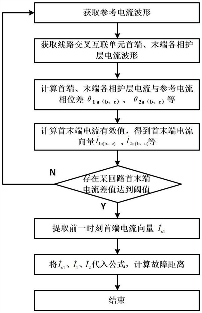
[0059] This embodiment discloses a method for detecting ground faults in the sheath, which is applied to the sheath of high-voltage transmission cables, such as figure 1 As shown, the applied high-voltage transmission cable circuit diagram is as follows Figure 4 shown, Figure 4 It is a section, and the sheath current is transposed through the cross-interconnection grounding box 5 to form three sheath circulation loops A-B-C, B-C-A, and C-A-B. The first end of the cross-interconnection unit is grounded through the direct grounding box 4, and the sheath circulation at the head end The monitoring device 6, the end sheath circulation monitoring device 7 and the main core current monitoring device can monitor the current waveform in real time, and the sampling rate meets the calculation requirements.

[0060] The detection method steps include:

[0061] S1: Obtain the reference current waveform, the reference current is the main core current, and the main core current can be ob...

Embodiment 2

[0077] The method for locating the grounding fault of the protective layer uses the section that detects the fault as in the first embodiment to locate the specific fault location, and the steps of the positioning method include:

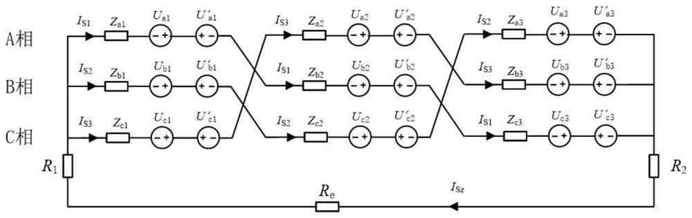
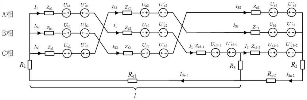
[0078] Obtain the loop current of the section before the fault occurs, the head current of the section after the fault occurs, and the end current of the section after the fault occurs, such as figure 2 , image 3 As shown, there are three loops A-B-C, B-C-A, and C-A-B for the sheath current through the cross interconnection, assuming that a single-phase ground fault occurs in the A-B-C loop. In the picture I s1 is the loop current before the fault occurs; Z ai ,Z bi ,Z ci (1≤i≤3) is the line sheath impedance of each section; L 1 , L 2 , L 3 is the length of each line; U ai , U bi , U ci (1≤i≤3) is the current induced voltage of the wire core, U′ ai , U' bi , U' ci (1≤i≤3) is the induced voltage of the sheath current, I s1 , I s2 , I...

Embodiment 3

[0099] This embodiment discloses a protective layer ground fault detection system. This embodiment is to realize the protective layer ground fault detection method as in Embodiment 1, including a first waveform acquisition module, a second waveform acquisition module, a first calculation module, and a second waveform acquisition module. 2. Calculation module and judgment module;

[0100] The first waveform acquisition module is used to acquire a reference current waveform, and the reference current is the main core current of the main power supply line in the same channel;

[0101] The second waveform acquisition module is used to select any section, and respectively acquire the head-end current waveform and the end-end current waveform of each cross-interconnection loop in the section, and the head-end current waveform is the incoming call side in the cross-interconnection loop The current waveform in the direction, the terminal current waveform is the current waveform in the...


PUM


Abstract

The invention discloses a protective layer grounding fault detection method, a positioning method, a detection system and a positioning system. The protective layer grounding fault detection method method comprises the following steps: acquiring a reference current waveform; acquiring a head end current waveform and a tail end current waveform of each section; taking the reference current wave as a zero phase, and based on the head-end current waveform and the tail-end current waveform, obtaining a first phase difference between the head-end sheath current and the reference current and a second phase difference between the tail-end sheath current and the reference current; adopting a fast Fourier transform method to obtain a current vector of a head-end protective layer and a current vector of a tail-end protective layer; and performing difference calculation on the current vector of the head-end protective layer and the current vector of the tail-end protective layer, and if the difference is greater than a preset threshold value, judging that the section has defects. The method has the beneficial effects that the fault can be identified at the first time when the protective layer fault occurs, and the fault position can be accurately positioned; the circulating current monitoring method is mature, the troubleshooting time of the sheath of the high-voltage transmission cable is effectively shortened, and the safety and stability of line operation are improved.

Description

technical field [0001] The invention relates to the technical field of cable sheath ground faults, in particular to a detection method, a positioning method, a detection system and a positioning system for a sheath ground fault. Background technique [0002] At present, the sheath fault location and ranging methods of power cables can be divided into online location and offline location methods. The traditional offline location methods are mainly comprehensive application of bridge method, acousto-magnetic synchronization method, step voltage method and so on. Bridge method: This method uses the bridge principle to measure the fault location by calculating the resistance of the grounding cable. But this method is not suitable for sheath fault location due to its poor anti-interference ability. Acousto-magnetic synchronization method: This method uses high-voltage equipment to make the cable fault click through and discharge, uses the receiver to record the discharge sound, ...

Claims


Application Information

Patent Timeline
Patent Type & Authority Applications(China)
IPC IPC(8): G01R31/52G01R31/58
CPCG01R31/52G01R31/58
Inventor 徐忠林丁玉琴腾小军苟杨胡勇饶显杰徐浩杨永鹏
Owner 徐忠林
Why Eureka
Try Eureka