Vacuumizing exhaust equipment for low-light-level image intensifier production

A technology of low-light image intensifier and exhaust equipment, which is applied in the direction of electric tube/lamp exhaust, etc., can solve the problems of complicated operation and high labor intensity of staff, and achieve the effect of reducing labor intensity and meeting pressure requirements.

Pending Publication Date: 2022-02-11
毛海军
View PDF0 Cites 0 Cited by
  • Summary
  • Abstract
  • Description
  • Claims
  • Application Information

AI Technical Summary

Problems solved by technology

[0004] In view of the above situation, in order to overcome the defects of the prior art, the present invention provides vacuum exhaust equipment for the production of low-light image intensifiers, which effectively solves the process of fixing and aligning picture tubes generally manually, and the operation is relatively cumbersome. , and the labor intensity of the staff is relatively high

Method used


Image

  • Vacuumizing exhaust equipment for low-light-level image intensifier production
  • Vacuumizing exhaust equipment for low-light-level image intensifier production
  • Vacuumizing exhaust equipment for low-light-level image intensifier production

Examples


Embodiment 1

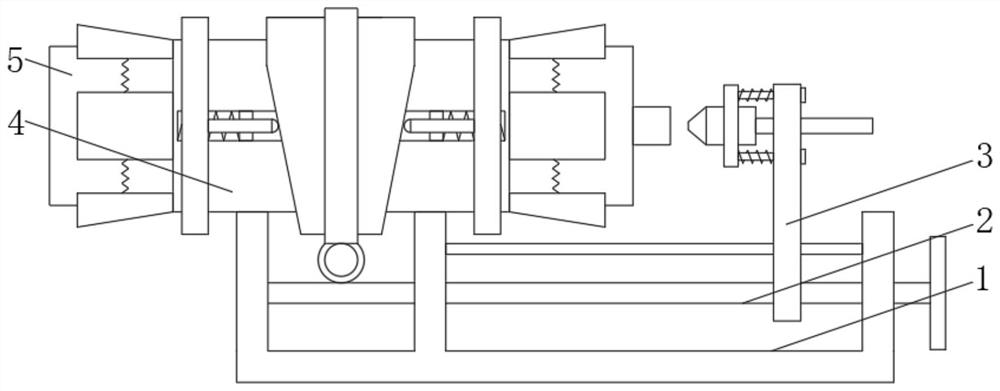
[0028] Embodiment one, by Figure 1-8 Provided, the present invention includes a mounting frame 1, a driving assembly 2 is installed inside the mounting frame 1, a vacuum assembly 3 is installed at one end of the driving assembly 2, a positioning assembly 4 is installed at the other end of the driving assembly 2, and the inside of the positioning assembly 4 A picture tube 5 is placed, and the positioning assembly 4 is connected with the installation frame 1;

[0029] The drive assembly 2 can drive the positioning assembly 4 to position and clamp the picture tube 5, and at the same time drive the vacuum assembly 3 to align with the picture tube 5, so that it is convenient for the staff to connect the vacuum assembly 3 and the picture tube 5, thereby improving the work efficiency of the staff .

Embodiment 2

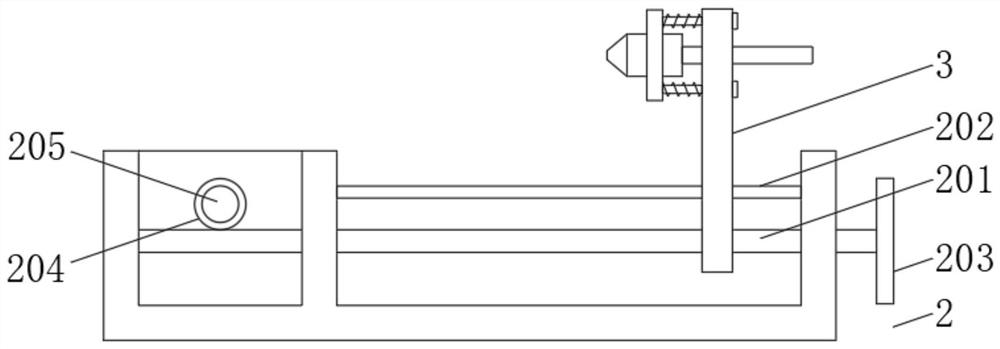
[0030] Embodiment 2, on the basis of Embodiment 1, the drive assembly 2 includes a drive worm 201 that is rotatably connected to the mounting frame 1, and a guide rod 202 connected to the mounting frame 1 is provided above the drive worm 201, and one end of the drive worm 201 is installed There is a rotating rod 203, the other end of the driving worm 201 is meshed with a driving worm gear 204, the driving worm gear 204 is installed on the driven worm 205, and the driven worm 205 is rotatably mounted on the mounting frame 1;

[0031] By rotating the rotating rod 203, the rotating rod 203 drives the driving worm 201 to rotate, and the driving worm 201 drives the vacuum assembly 3 to move through threads, making it gradually approach the picture tube 5, while the driving worm 201 drives the driving worm gear 204 to rotate by means of meshing , the driving worm gear 204 drives the coaxial driven worm 205 to rotate, and the driven worm 205 drives the positioning assembly 4 to clamp ...

Embodiment 3

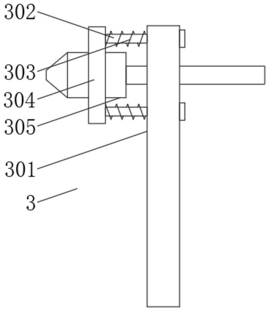
[0032] Embodiment 3, on the basis of Embodiment 1, the vacuum assembly 3 includes a moving plate 301 threadedly connected to the driving worm 201, a positioning rod 302 is inserted symmetrically on the moving plate 301, and a positioning spring is sleeved on the positioning rod 302 303, the positioning rod 302 is symmetrically installed on the mounting plate 304, the mounting plate 304 is equipped with a joint 305, the joint 305 is connected with an external vacuum pump, and the bottom of the moving plate 301 is respectively provided with a screw hole and a guide hole, and the screw hole is threaded with the driving worm 201 connection, the guide hole is socketed with the guide rod 202;

[0033] The active worm 201 drives the moving plate 301 to move, and the moving plate 301 drives the joint 305 on the mounting plate 304 to move close to the picture tube 5, so that it is convenient for the staff to connect the two together, and finally vacuumize through an external vacuum pump...


PUM


Abstract

The invention relates to the technical field of low-light-level image intensifiers, and discloses vacuumizing exhaust equipment for low-light-level image intensifier production, which solves the problems that the fixation and alignment process of a kinescope is generally realized in a manual mode, the operation is relatively tedious, and the labor intensity of workers is relatively high. The equipment comprises a mounting frame, a driving assembly is mounted in the mounting frame, a vacuumizing assembly is mounted at one end of the driving assembly, a positioning assembly is mounted at the other end of the driving assembly, a kinescope is placed in the positioning assembly, and the positioning assembly is connected with the mounting frame. Through the cooperative use of the positioning assembly, the vacuumizing assembly, the driving assembly and the like, the driving assembly can simultaneously drive the positioning assembly and the vacuumizing assembly to move, the kinescope is fixed through the positioning assembly, and then the vacuumizing assembly gets close to the kinescope, so that the kinescope fixing and aligning process can be automatically completed; and the labor intensity of workers is reduced.

Description

technical field [0001] The invention belongs to the technical field of low-light image intensifiers, in particular to vacuum exhaust equipment for the production of low-light image intensifiers. Background technique [0002] The low-light image intensifier, also known as the low-light image tube, is the core device of the low-light night vision device and plays a decisive role in the imaging quality of the entire system. The low-light image intensifier is the core component of the low-light night vision system. The entire low-light night vision system includes an optical imaging lens group, a low-light image intensifier, and a post-processing system. Among them, the low-light image intensifier is the most important part. So far, there have been first-generation low-light image intensifiers, second-generation low-light image intensifiers, third-generation low-light image intensifiers, and fourth-generation low-light image intensifiers. Different generations of low-light imag...

Claims


Application Information

Patent Timeline
Patent Type & Authority Applications(China)
IPC IPC(8): H01J9/385
CPCH01J9/385
Inventor 毛海军
Owner 毛海军
Why Eureka
Try Eureka