High-capacity battery system for locomotive

A battery system and large-capacity technology, which is applied to locomotives, batteries, secondary batteries, etc., can solve the problems of small power battery system capacity, large fuel consumption, polluted gas, and low energy of the battery system, so as to improve heat dissipation performance and reduce heat dissipation. Proliferation risk, effect of high degree of integration

Pending Publication Date: 2022-02-11
CRRC QISHUYAN CO LTD
View PDF0 Cites 0 Cited by
  • Summary
  • Abstract
  • Description
  • Claims
  • Application Information

AI Technical Summary

Problems solved by technology

[0002] At present, the use of power battery systems in the rail transit industry is still in the initial stage, and the energy of the battery systems used is relatively low. Most of them are used for auxiliary power supply. With the requirements of national policies, for the original simple use of high-power diesel engines for traction operations, It will consume a large amount of fuel and produce a large amount of polluting gas, which will pollute the atmosphere and affect the living environment. Therefore, there is an urgent demand for energy-saving and environmentally friendly diesel locomotives. The power battery system with large capacity and high power has begun to be used to replace diesel engines to reduce fuel consumption. Realize the purpose of energy saving and environmental protection
[0003] At present, the power battery system used in the automobile industry and the rail transit industry has a small capacity, and the environmental conditions used are also different, so it cannot be used directly

Method used


Image

  • High-capacity battery system for locomotive
  • High-capacity battery system for locomotive
  • High-capacity battery system for locomotive

Examples


Embodiment Construction

[0039] The present invention will now be described in further detail in conjunction with the accompanying drawings and preferred embodiments. These drawings are all simplified schematic diagrams, which only illustrate the basic structure of the present invention in a schematic manner, so they only show the configurations related to the present invention.

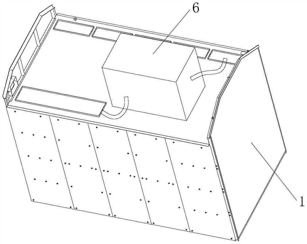
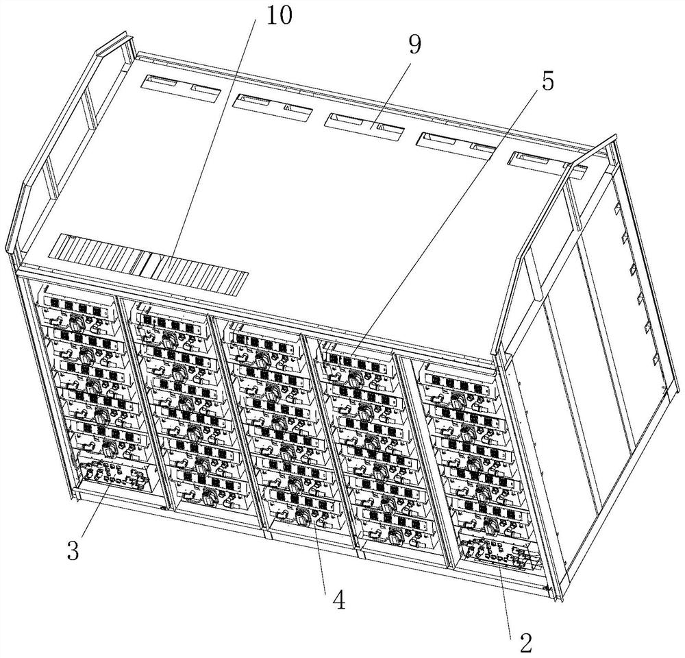
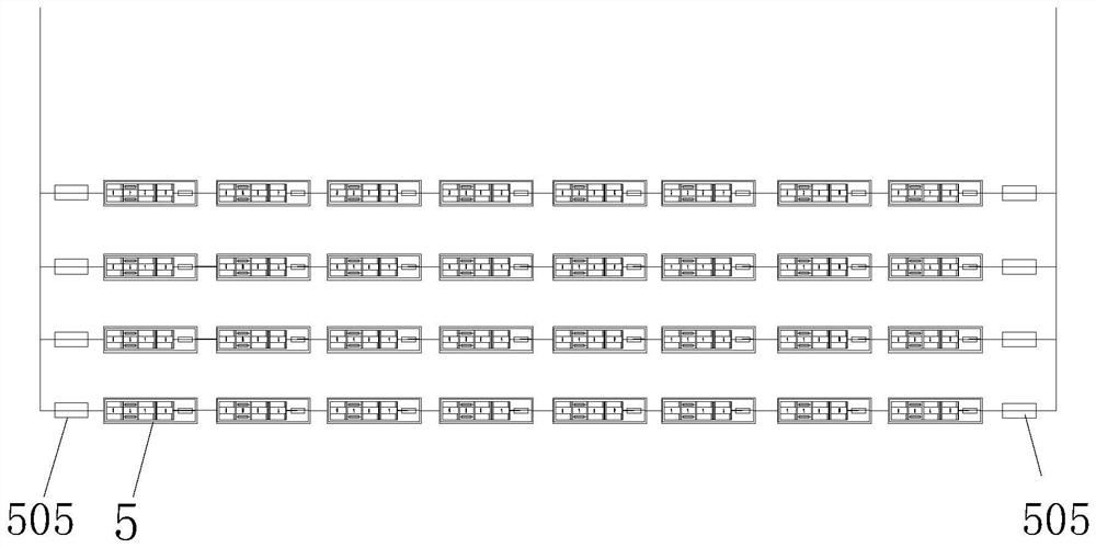
[0040] Such as Figure 1-10 A large-capacity battery system for a locomotive is shown, including a battery assembly and a fuse protection assembly, which improves the safety performance of the battery system; the battery assembly includes a positive high-voltage box 2, a negative high-voltage box 3, and a control battery system The box body 4 and the power battery assembly; the power battery assembly includes four power battery units connected in parallel, and each power battery unit is connected in series by eight power battery packs 5; the positive pole of the power battery assembly is connected to the positive high-voltag...


PUM


Abstract

The invention relates to a high-capacity battery system for a locomotive. The high-capacity battery system for the locomotive comprises a battery assembly and a fusing protection assembly, and the safety performance of the battery system is improved by the fusing protection assembly; and the fusing protection assembly comprises a system anode fuse, a battery pack fuse, a module connecting copper bar, a bus copper bar, a fuse wire group and a battery cell protector; and fusing current values of the fusing protection assembly are arranged as follows: the system anode fuse < the battery pack fuse < the module connecting copper bar < the bus copper bar < the fuse wire < the battery cell protector. The structure is simple, the positive electrode high-voltage box, the negative electrode high-voltage box, the control battery system box body, the power battery assembly and the heat guarantee system are placed in a centralized mode, an integral mounting frame is adopted, mounting is easy and convenient, and the integration degree is high; and a six-layer fusing safety design is adopted, and fusing current values allowed to pass through by different parts in the fusing protection assembly are different, so that fusing current protection of each level is realized.

Description

technical field [0001] The invention relates to the technical field of locomotive battery systems, in particular to a large-capacity battery system for locomotives. Background technique [0002] At present, the use of power battery systems in the rail transit industry is still in the initial stage, and the energy of the battery systems used is relatively low. Most of them are used for auxiliary power supply. With the requirements of national policies, for the original simple use of high-power diesel engines for traction operations, It will consume a large amount of fuel and produce a large amount of polluting gas, which will pollute the atmosphere and affect the living environment. Therefore, there is an urgent demand for energy-saving and environmentally friendly diesel locomotives. The power battery system with large capacity and high power has begun to be used to replace diesel engines to reduce fuel consumption. To achieve the purpose of energy saving and environmental p...

Claims


Application Information

Patent Timeline
IPC IPC(8): H01M50/583H01M10/613H01M10/663H01M50/507B61C17/06
CPCH01M50/583H01M50/507H01M10/613H01M10/663B61C17/06H01M2220/20Y02E60/10Y02T30/00
Inventor 黄敬云庞立民裴斌王雄海吴宏军陈卫蒋一诚袁波
Owner CRRC QISHUYAN CO LTD
Why Eureka
Try Eureka