
Machining process for thin-wall cylindrical part with boss in inner hole

A mechanical processing, cylindrical technology, applied in the field of mechanical processing, can solve the problems of long slotting processing time, large processing allowance, poor cutting state, etc., and achieve the advantages of saving processing time, large processing allowance and long processing time Effect

Pending Publication Date: 2022-02-15
HENAN NORTHERN HONGYANG ELECTROMECHANICAL CO LTD
View PDF0 Cites 0 Cited by
  • Summary
  • Abstract
  • Description
  • Claims
  • Application Information

AI Technical Summary

Problems solved by technology

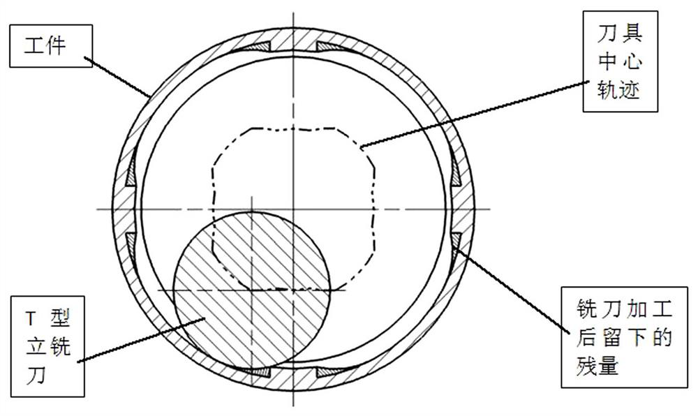
(Tube body) The parallelism of both end surfaces does not meet the requirement of 0.02mm; 2. The inner shape is difficult to remove iron chips when processed by ordinary CNC lathe, the cutting state is poor, and the surface roughness of the inner hole does not meet the requirement of 1.6; 3. Thin wall Cylindrical parts are affected by factors such as multiple clamping errors, machining deformation, and clamping deformation. When slotting the boss of the inner hole of the workpiece, there is a certain deviation between the center of the machining coordinate system and the actual center of the inner hole. As a result, the slotting processing surface does not coincide with the turning processing surface, resulting in overcut or residual
Therefore, in the actual machining, it is time-consuming and labor-intensive to follow the semi-finishing allowance, stop the measurement, judge the deviation, adjust the center of the coordinate system, modify the program, and repeat the above steps many times until the inner hole boss is processed into a finished product; 4. Turning When the final workpiece is directly slotted, the machining allowance is large, and it takes a lot of time to roughly insert the amount, resulting in a long overall slotting time and low slotting efficiency

Method used


Image

  • Machining process for thin-wall cylindrical part with boss in inner hole
  • Machining process for thin-wall cylindrical part with boss in inner hole
  • Machining process for thin-wall cylindrical part with boss in inner hole

Examples


Embodiment Construction

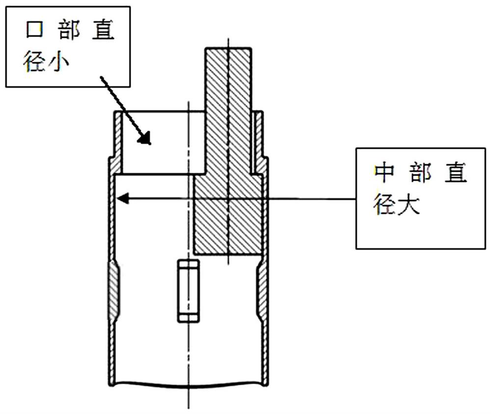
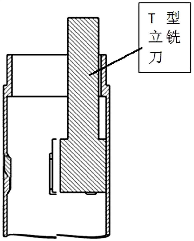
[0022] The specific implementation manners of the present invention will be described in detail below in conjunction with the accompanying drawings. Such as Figure 1-5 Shown: a machining process for a thin-walled cylindrical part with a boss in the inner hole, including the following steps:

[0023] Step 1. First complete the rough turning inner shape of the pipe body-rough turning shape-half turning outer circle datum of the pipe body on an ordinary numerical control lathe;

[0024] Step 2. Select four-axis processing equipment with a turntable or dividing head, and use self-made special fixtures to wrap the semi-circular part of the tube body workpiece. After one clamping, perform fine boring at both ends of the inner shape-milling inner shape-milling The inner product of the boss - the chamfering finished product at both ends of the milling boss - the step of inserting the boss;

[0025] Step 3: Use a common CNC lathe to finely bore the end faces of both ends of the pipe...


PUM


Abstract

The invention discloses a machining technology for a thin-wall cylindrical part with a boss in an inner hole. The machining process comprises the following steps: step 1, completing rough turning of the inner shape, rough turning of the outer shape and semi-turning of the outer circle datum of a pipe body on a common numerical control lathe; and step 2, selecting four-axis machining equipment with a rotary table or a dividing head, and wrapping the semi-turning outer circle part of the pipe body workpiece with a self-made special clamp. The machining process effectively solves the problems that: the two ends of the inner shape of a pipe body workpiece are subjected to multi-pass finish turning machining through a common numerical control lathe, due to the influence of multiple clamping errors and machining and clamping deformation factors,the machining precision is poor, scrap iron discharging is difficult, the cutting state is poor, a slotting machining face and a turning machining face do not coincide, and shutdown measurement, deviation value judgment, coordinate system center adjustment, program modification, relatively large machining allowance and a lot of time for roughly interpolating the allowance are caused by semi-finish machining allowance in actual machining.

Description

technical field [0001] The invention belongs to the technical field of machining, and in particular relates to a machining process of a thin-walled cylindrical part with a boss in an inner hole. Background technique [0002] The inner hole boss of the part is a common and important structure in mechanical design. The tube part is a thin-walled cylindrical part made of aluminum alloy. The inner shape structure is special and the precision is high. According to the comprehensive and multi-angle analysis of the drawing size, structural characteristics and processing route of the body part, it is found that the processing of the inner hole boss and the chamfering on both sides of the boss is the processing difficulty of the whole part; the original mechanical processing route is: Ordinary CNC lathe rough turning outer circle - rough turning inner hole at the left end - rough turning right end inner hole - semi-finishing outer circle - finishing turning left end inner hole - fini...

Claims


Application Information

Patent Timeline
Patent Type & Authority Applications(China)
IPC IPC(8): B23P15/00
CPCB23P15/00
Inventor 毛永王久源胡东蓬张敏琦
Owner HENAN NORTHERN HONGYANG ELECTROMECHANICAL CO LTD
Learn More