
Forming device provided with anti-collision structure and used for sliding rail machining

A molding device and anti-collision technology, which is applied in the direction of electrode structure, dry gas arrangement, lighting and heating equipment, etc., can solve the problems of incomplete coverage of electroplating solution, inability to contact hot air in time, low processing efficiency and quality, and prevent Insufficient protective layer thickness, convenient loading and unloading, and avoiding collision effects

Pending Publication Date: 2022-02-15
东莞市联海自动化科技有限公司
View PDF0 Cites 0 Cited by
  • Summary
  • Abstract
  • Description
  • Claims
  • Application Information

AI Technical Summary

Problems solved by technology

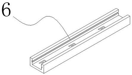
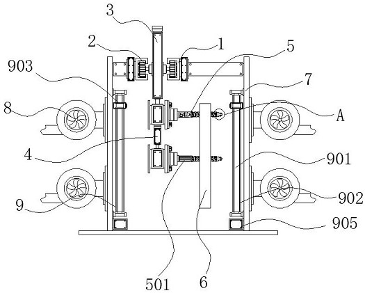
[0004] Aiming at the deficiencies of the prior art, the present invention provides a molding device with an anti-collision structure for processing slide rails, which solves the above-mentioned problem in the background technology that the existing slide rails are mostly hung on hooks during electroplating and drying. Enter the electroplating device and drying device to accept the work, but the contact between the hook and the inner wall of the hole of the slide rail leads to incomplete coverage of the electroplating solution, and at the same time, the hot air cannot contact the covered part of the hook in time during drying, resulting in low processing efficiency and quality The problem

Method used


Image

  • Forming device provided with anti-collision structure and used for sliding rail machining
  • Forming device provided with anti-collision structure and used for sliding rail machining
  • Forming device provided with anti-collision structure and used for sliding rail machining

Examples


Embodiment Construction

[0027] The technical solutions in the embodiments of the present invention will be clearly and completely described below with reference to the accompanying drawings in the embodiments of the present invention. Obviously, the described embodiments are only a part of the embodiments of the present invention, but not all of the embodiments.

[0028] In the description of the present invention, unless otherwise stated, "plurality" means two or more; the terms "upper", "lower", "left", "right", "inner", "outer" The orientation or positional relationship indicated by , "front end", "rear end", "head", "tail", etc. are based on the orientation or positional relationship shown in the accompanying drawings, and are only for the convenience of describing the present invention and simplifying the description, not Indicates or implies that the referred device or element must have a specific orientation, be constructed and operate in a specific orientation, and therefore should not be cons...


PUM


Abstract

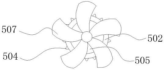
The invention discloses a forming device provided with an anti-collision structure and used for sliding rail machining and belongs to the technical field of sliding rail machining. The forming device comprises a fixed sliding rail, hanging auxiliary mechanisms and hot air filtering mechanisms; an electric control slide wheel is arranged in the fixed sliding rail; the hanging auxiliary mechanisms are fixed to the bottom of the side face of a main electric push rod and the bottom of the side face of an auxiliary electric push rod; the outer wall of each placement hanging piece is sleeved with a sliding rail body; the hot air filtering mechanisms are arranged on the two sides of the inner wall of a drying box; a dust storage box is arranged below an electric control tackle; and the dust storage box is fixedly connected with the drying box. According to the forming device provided with the anti-collision structure and used for sliding rail machining, fan blades rotate through a waterproof motor, the fan blades are unfolded under the action of centrifugal force so that an electroplating solution and hot air can be guided, the sliding rail body can make full contact with the electroplating solution and the hot air, and after stopping rotation, the fan blades are folded through a micro torsional spring, and therefore, the sliding rail body can be conveniently loaded and unloaded.

Description

technical field [0001] The invention relates to the technical field of slide rail processing, in particular to a forming device with an anti-collision structure for slide rail processing. Background technique [0002] Slide rails are often used for household tools such as doors, windows and drawers to facilitate the opening and closing of doors, windows and drawers. The slide rail needs to undergo electroplating and drying processes during the processing process. The surface of the electroplated slide rail produces a protective layer, thereby extending the slide rail. Long service life to avoid corrosion, oxidation and rust. [0003] During electroplating and drying, the existing slide rails mostly enter the electroplating device and the drying device by hanging on the hook to accept the operation, but the contact between the hook and the inner wall of the hole groove of the slide rail leads to incomplete coverage of the electroplating solution. The hot air cannot reach the...

Claims


Application Information

Patent Timeline
Patent Type & Authority Applications(China)
IPC IPC(8): C25D17/08F26B21/00F26B25/00B03C3/04B03C3/47B03C3/74
CPCC25D17/08F26B21/003F26B21/004F26B21/006F26B25/003B03C3/04B03C3/47B03C3/743
Inventor 陈海华李晓霞曾芬妮
Owner 东莞市联海自动化科技有限公司
Features
  • Generate Ideas
  • Intellectual Property
  • Life Sciences
  • Materials
  • Tech Scout
  • Unparalleled Data Quality
  • Higher Quality Content
  • 60% Fewer Hallucinations
Learn More