Structure with water collecting and storing functions in water-deficient or pluvial area

A structure and water collection technology, which is applied in the direction of drainage structures, building structures, buildings, etc., can solve the problems of large pouring volume of beam-slab-column structures, inability to play the role of rain and flood, drought regulation, and unfavorable sustainable development, so as to save project occupation Land and economic costs, the effect of alleviating urban waterlogging problems, and alleviating drought and water shortage problems

Pending Publication Date: 2022-02-15
HUBEI PROVINCIAL WATER RESOURCES & HYDROPOWER PLANNING SURVEY & DESIGN INST
View PDF0 Cites 0 Cited by
  • Summary
  • Abstract
  • Description
  • Claims
  • Application Information

AI Technical Summary

Problems solved by technology

[0002] Existing water conservancy engineering facilities such as reservoirs and collection pools are susceptible to many influences such as topography, geographical climate, and soil deposition, resulting in short service life, large construction funds, and long construction periods, which cannot maximize the impact of rain, floods, and droughts. Regulatory function, when the rainstorm hits, the waste of water resources will be lost in vain, and it will not be able to play a timely scheduling role in the drought and water shortage
At present, the storage tanks and collection tanks mainly have the following problems: the function is single and lacking, and there is basically no other place except for simple storage and drainage functions, which leads to low utilization rate; due to the limitation of concrete materials, some structures cannot be made Lightweight and uniquely shaped structures, and the beam-slab-column structure part is poured in a large volume and occupies a large space; construction requires excavation and a construction work surface is required. If the site conditions are limited, there is no construction work surface and construction cannot be performed; it cannot be recycled and utilized , the extensive application of concrete has brought a great burden to the environment. When these reservoirs and sumps are abandoned, a large amount of land resources have to be used to dispose of these materials, and the energy consumption of concrete recycling is extremely serious; each sump, There is no fixed size for the reservoirs, and there is no batch and modular combination method, which increases the project cost; limited by the objective factors of materials and labor, the construction cost is often too high and the production period is long; this kind of engineering shape often gives people formal The image of heavy and rigid reinforced concrete; traditional building materials consume a lot of energy and have a large environmental load, which is not conducive to sustainable development

Method used


Image

  • Structure with water collecting and storing functions in water-deficient or pluvial area
  • Structure with water collecting and storing functions in water-deficient or pluvial area
  • Structure with water collecting and storing functions in water-deficient or pluvial area

Examples


example 1

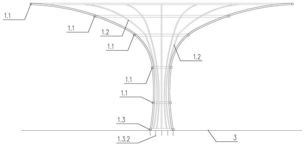
[0058] like Figure 8 As shown, due to the functional requirements of the present invention, it should be in a rainy or water-scarce area. Considering the topography and climatic conditions, it is necessary to consider further fixing in the face of extremely bad weather. The wind line 3.1 can be used to fix the ground, mountain body or obstacle 4, finally forming a stable structural form.

example 2

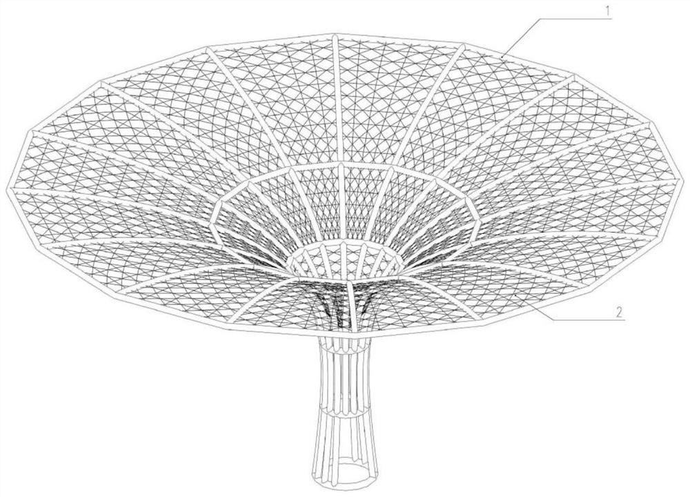
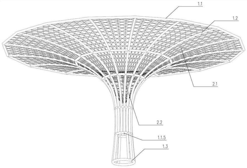
[0060] like Figure 9 As shown, after the present invention is fixed, when the air 4.1 flows, the mist, dew, snow, frost and the water vapor contained in the air in the air 4.1 encounter the mesh wire formed by the water collection net 2.1 in the flow process, and liquefy or "sticky". Connected to the mesh to form small water droplets, absorb the moisture contained in the air 4.1, and use the formed mesh to expand the surface area, increase the contact area with the air 4.1, increase the water absorption, and quickly transfer to the lower diversion layer 2.2.

[0061] like Figure 10 As shown, the diversion layer 2.2 is funnel-shaped, the upper part is connected to the water collection net 2.1, and the lower part is a tapered opening, made of nylon, and the whole is in a tight state to ensure that the formed water droplets and water flow can be smoothly diverted to the lower collection container 4.3 Or carry out organized collection in the diversion tube 4.4.

example 3

[0063] When it rains, the rainwater 4.2 is diverted to the lower diversion layer 2.2 along the funnel shape of the catchment net 2.1, wherein the hexagonal braided surface of the catchment net 2.1 is perpendicular to the ground, ensuring that the rainwater 4.2 can be diverted along the weaving direction .

[0064] The diversion layer 2.2 is funnel-shaped, the upper part is connected to the water collection net 2.1, and the lower part is a tapered opening, made of nylon, and the whole is in a tight state to ensure that the formed water droplets and water flow can be smoothly diverted to the lower collecting container 4.3 or diversion Tissue collection is performed within tube 4.4.


PUM


Abstract

The invention discloses a structure with water collecting and storing functions in a water-deficient or pluvial area. The whole structure is in a Y shape and comprises a framework system with the top penetrating to the bottom and a water collecting system with the top penetrating to the middle, wherein the framework system comprises a plurality of cross beams, a plurality of stand columns and an adjusting ground beam, the adjusting ground beam is annular, one part of the stand columns are fixed to the adjusting ground beam at the bottom, upper portions of the multiple stand columns are in a horn scattering shape, and the middle portions of the multiple stand columns are in a waist shrinking shape; the water collecting system comprises a water collecting net and a flow guide layer, the water collecting net is fixed to the upper cross beam, and an upper portion of the flow guide layer is connected with the water collecting net and fixed to the lower cross beam. According to the structure, the whole shape is Y-shaped, and water in rain, fog, dew, snow, frost and the like can be adhered to a water collecting system by utilizing an upper opening of the Y shape, so the water can flow to the lower part by utilizing the arc shape of the water collecting system.

Description

technical field [0001] The invention belongs to the technical fields of water conservancy engineering, ecological engineering and garden landscape, and in particular relates to a structure with the function of collecting and storing water in water-deficient or rainy areas. Background technique [0002] Existing water conservancy engineering facilities such as reservoirs and collection pools are susceptible to many influences such as topography, geographical climate, and soil deposition, resulting in short service life, large construction funds, and long construction periods, which cannot maximize the impact of rain, floods, and droughts. Regulatory function, when the rainstorm hits, the waste of water resources is caused by the in vain loss, and it cannot play a timely dispatching role when there is a drought and water shortage. At present, the storage tanks and collection tanks mainly have the following problems: the function is single and lacking, and there is basically no...

Claims


Application Information

Patent Timeline
Patent Type & Authority Applications(China)
IPC IPC(8): E04B1/00E04B1/343E04B1/38E04B1/64E04B1/92E03B3/02E03F5/10E04D13/04E04G21/14
CPCE04B1/00E04B1/34315E04B1/34384E04B1/38E04B1/642E04B1/92E03B3/02E03F5/10E03F5/105E04D13/0404E04D13/0481E04G21/14E04B2001/0053E04D2013/0495Y02A20/108
Inventor 徐昕刘昱陈诺
Owner HUBEI PROVINCIAL WATER RESOURCES & HYDROPOWER PLANNING SURVEY & DESIGN INST
Why Eureka
Try Eureka