Capacitive voltage division soft switching inverter for current conversion action point bias voltage switching

A technology of bias voltage and capacitive voltage division, which is applied in the direction of conversion equipment without intermediate conversion to AC, conversion devices for adjusting electrical variables, and output power, etc., can solve the problems of large transformer core volume and high voltage stress, and achieve improvement Efficiency and Power Density, Cost Reduction and EMI Effects

Pending Publication Date: 2022-02-15
SHANXI UNIV
View PDF0 Cites 0 Cited by
  • Summary
  • Abstract
  • Description
  • Claims
  • Application Information

AI Technical Summary

Problems solved by technology

The transformer core cannot be reset within one switching cycle. The selected transformer core is bulky and requires two sets of auxiliary circuits to realize the auxiliary commutation work of the main switch under bidirectional current output; and the auxiliary commutation diode has no clamping measures, and the overcharge vibration Bells cause high voltage stress and EMI

Method used


Image

  • Capacitive voltage division soft switching inverter for current conversion action point bias voltage switching
  • Capacitive voltage division soft switching inverter for current conversion action point bias voltage switching
  • Capacitive voltage division soft switching inverter for current conversion action point bias voltage switching

Examples


Embodiment Construction

[0100] In order to make the purpose, technical solutions and advantages of the present invention clearer, the present invention will be further described in detail below in conjunction with the accompanying drawings and embodiments. It should be understood that the specific embodiments described are only used to explain the present invention, but not to limit the present invention. Based on the embodiments of the present invention, all other embodiments obtained by those skilled in the art without creative efforts shall fall within the protection scope of the present invention.

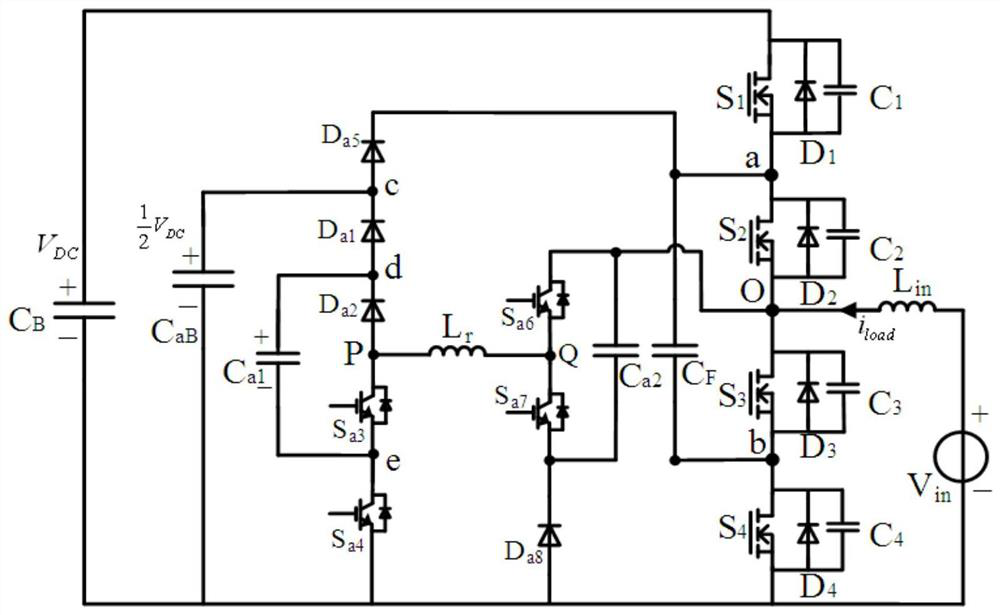
[0101] Such as figure 1 As shown, the present invention provides a capacitive voltage-dividing soft-switching inverter for switching the bias voltage at the commutation action point, including: a first main switching tube S 1 , the second main switch S 2 , the third main switch S 3 , the fourth main switch S 4 , flying capacitor C F , Main circuit DC bus capacitor C B , Auxiliary circuit DC bus ...


PUM


Abstract

The invention discloses a capacitive voltage division soft switching inverter for current conversion action point bias voltage switching. ZVS conduction of a main loop switch and ZCS conduction of an auxiliary loop switch can be achieved. And through bias voltage switching of a commutation action point, high and low states of the input voltage are adapted. Charge balance enables a capacitance voltage dividing point to maintain a constant voltage state. The efficiency and the power density are effectively improved, and the cost and the EMI are reduced.

Description

technical field [0001] The invention relates to the technical field of power electronic conversion, in particular to a capacitive voltage-dividing soft-switching inverter for switching the bias voltage at the commutation action point. Background technique [0002] Power factor correction PFC is usually used to improve power factor PF and reduce total harmonic distortion. Among many PFC circuits, Boost converter is widely used because of its simple structure, continuous input current and strong uniformity of characteristics. Among them, the bridgeless Boost PFC reduces the conduction loss by reducing the number of semiconductor devices on the working circuit, so as to improve the efficiency. However, the problem of switching loss in bridgeless PFC is prominent. When the switching frequency is increased, the switching loss in the circuit will increase accordingly, especially when the circuit works in CCM, the reverse recovery current of the freewheeling diode will increase th...

Claims


Application Information

Patent Timeline
IPC IPC(8): H02M3/07H02M3/158H02M7/537H02M1/42
CPCH02M3/07H02M3/158H02M7/537H02M1/4241H02M1/4225Y02B70/10
Inventor 禹健樊启航
Owner SHANXI UNIV
Why Eureka
Try Eureka