Grinding roller device of medium-speed mill

A technology of coal pulverizers and grinding rollers, which is applied in the direction of grain processing, etc., can solve the problems of thread wear, small size, and poor blowback effect of the hinge seat, so as to increase the outlet airflow velocity, increase the labyrinth seal structure, improve the The effect of wind pressure distribution

Active Publication Date: 2022-02-18
CHINA UNIV OF MINING & TECH
View PDF6 Cites 0 Cited by
  • Summary
  • Abstract
  • Description
  • Claims
  • Application Information

AI Technical Summary

Problems solved by technology

The currently used grinding rollers of coal mills have the following deficiencies: First, because the sealing air enters from the top of the roller shaft, the shielding of the roller shaft leads to uneven distribution of the sealing air and poor blowback effect, which cannot ensure the sealing of the root of the grinding roller. The fine-grained material enters the grinding roller bearing cavity through the root of the grinding roller, causing rapid wear of the bearing and grinding roller jamming, increasing the frequency of mill jamming failures, increasing the frequency of shutdown maintenance and equipment maintenance costs
Secondly, the oil seal is a vulnerable part, and the oil seal is directly connected to the bearing cavity, so that the damaged oil seal can easily enter the bearing cavity and affect the bearing.
Thirdly, the installation and positioning of the roller sleeve is not accurate, and it is easy to be installed incorrectly; the thread of the shaft seat is easy to be worn due to the collision of the grinding roller when the grinding roller is disassembled, and it cannot be reinstalled, which requires a lot of man-hours to process
Finally, due to the compact structure and small size of the semi-industrial mill, the mill separator must be hoisted and disassembled for oil filling and maintenance of the grinding roller bearing cavity, which greatly increases the maintenance workload and difficulty

Method used


Image

  • Grinding roller device of medium-speed mill
  • Grinding roller device of medium-speed mill
  • Grinding roller device of medium-speed mill

Examples


Embodiment Construction

[0033] The present invention will be further described below in conjunction with the embodiment in the accompanying drawings:

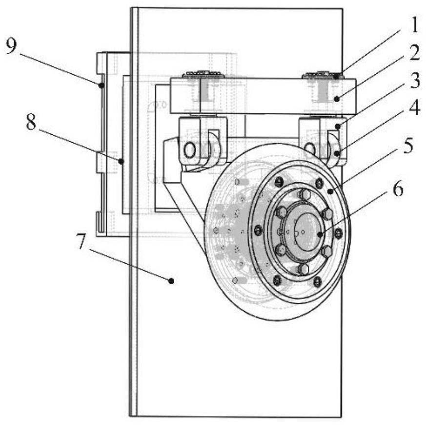
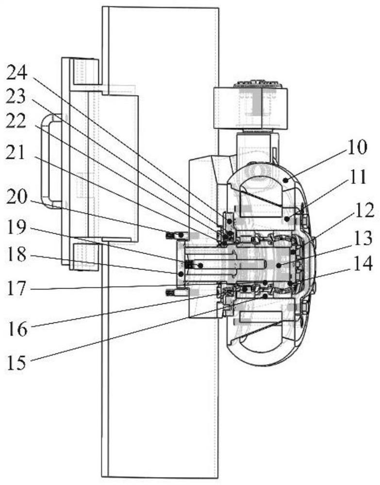
[0034] Such as figure 1 figure 2 As shown, a medium-speed coal mill roller device of the present invention is mainly composed of a shaft seat fixing part 1, a press frame 2, a shaft seat 3, a roll frame 4, a wedge ring 5, an end cover 6, and a mill Shell 7, observation window 8, observation window cover 9, self-aligning bearing 14, bearing outer spacer 15, roller bearing 16, bearing inner spacer 17, left pressure plate 18, roller core 11, axial air pipe 19, shaft sleeve 21 , a transparent cover 22, an oil seal 23 and a top cover 24; the press frame 2 arranged in the mill casing 7 is provided with a hinge seat fixture 1 connected to the hinge seat 3, and the hinge seat 3 is hinged with a roller frame 4 that can freely fine-tune the angle of the grinding roller when the grinding condition changes instantaneously. The sleeve 21 is provided with a roller...


PUM


Abstract

The invention discloses a grinding roller device of a medium-speed mill. The grinding roller device comprises a hinge shaft seat fixing piece, a roller frame, a shaft sleeve, a roller core, a right pressing plate, a roller shaft, a non-return sealing air short pipe and a transparent cover. According to the invention, damage to a mill hinge shaft seat during disassembly of a grinding roller is reduced through the hinge shaft seat fixing piece; the roller frame is provided with a sealing opening and the non-return sealing air short pipe is added, so that uniform distribution of air pressure of sealing air is promoted, and the dust prevention efficiency of the sealing air is improved; the right pressing plate, the roller shaft, an axis air pipe, the right pressing plate and the shaft sleeve form an oil injection and ash removal cavity, so that oil injection and ash removal operation on the grinding roller is facilitated; the shaft sleeve and the transparent cover form a group of labyrinth sealing structures, so that sealing performance of a root part of the grinding roller is enhanced; and a boss is arranged on one side of a large end of the roller core, so that the roller sleeve can be conveniently positioned during installation, an overhaul process of the grinding roller of a mill is simplified, an abrasion speed of a grinding roller bearing is reduced, disassembly and overhaul frequency of the mill is reduced, a daily maintenance period is shortened, and fault-free service time of a medium-speed mill is further prolonged.

Description

technical field [0001] The invention relates to a medium-speed coal mill grinding roller device, in particular to a semi-industrial roller vertical mill system suitable for the crushing and grading process of mineral materials. [0002] technical background [0003] By 2050, primary energy consumption still accounts for 66.3% of the world's energy structure, while coal accounts for 24.7% of total primary energy consumption, most of which are used for power generation. At the same time, coal consumption and consumption proportion have been at a high level for a long time, and the steady increase in the capacity of thermal power generators for 12 consecutive years also indicates that thermal power as the main power generation mode will not change for a long time. Inhalable particulate matter, sulfur oxides, and nitrogen oxides produced by coal combustion are one of the main causes of air pollution. How to achieve efficient coal utilization and energy conservation and environme...

Claims


Application Information

Patent Timeline
Patent Type & Authority Applications(China)
IPC IPC(8): B02C15/00B02C23/00
CPCB02C15/004B02C23/00
Inventor 张峰彬何亚群谢卫宁李金龙韦能张真兴
Owner CHINA UNIV OF MINING & TECH
Why Eureka
Try Eureka