Machining tool for metal sealing gasket

A metal sealing gasket and tooling technology, applied in the field of machining, can solve the problems of deviation or slipping off the workbench, high labor intensity of workers, poor safety, etc., to achieve the effect of improving sealing performance, facilitating processing operations, and improving stability

Active Publication Date: 2022-02-18
烟台长鑫密封产品有限公司
View PDF10 Cites 7 Cited by
  • Summary
  • Abstract
  • Description
  • Claims
  • Application Information

AI Technical Summary

Problems solved by technology

However, there are some defects in the tooling used for sealing gasket processing. For example, in actual production, the width of the metal sheet generally changes greatly. When the metal sheet is narrowed, it is easy to deviate or slip off during the operation The condition of the workbench affects the normal processing; in addition, the sealing gasket products after stamping and forming now need manual or additional equipment to discharge the material on the mold, the labor intensity of the workers is high, the safety is poor, and the cost is increased

Method used


Image

  • Machining tool for metal sealing gasket
  • Machining tool for metal sealing gasket
  • Machining tool for metal sealing gasket

Examples


Embodiment 1

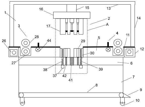
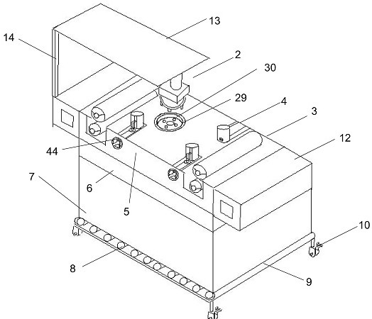
[0043] A metal sealing spacer, including a stamping chamber 1, a mold chamber 5, a receiving box 6, a table 11, further comprising a stamping mechanism 2, a feed mechanism 3, and a clamping mechanism 4, a stamping chamber on the table 11. 1, the stamping chamber 1 is composed of the top plate 13 and the four brackets 14 located on the table 11, and the stamping mechanism 2 is located on the top plate 13, and the bottom surface of the table 11 is connected to the mold cavity 5, and there is a control box on both sides of the mold cavity 5. 12, the mold cavity 5 is provided with a mold groove 29 and a portion of the mold groove 29 is covered with a table 11, and the table 11 and the mold cavity 5 are also provided with the feed mechanism 3 and the clamping mechanism 4, and the mold cavity 5 is below The box 6 is connected to the cassette 7, and the discharge box 7 is provided with a conveyed tape 8, and the conveyor tape 8 is provided with a discharge opening 9 at the interface of t...

Embodiment 2

[0045]A metal sealing spacer, including a stamping chamber 1, a mold chamber 5, a receiving box 6, a table 11, further comprising a stamping mechanism 2, a feed mechanism 3, and a clamping mechanism 4, a stamping chamber on the table 11. 1, the stamping chamber 1 is composed of the top plate 13 and the four brackets 14 located on the table 11, and the stamping mechanism 2 is located on the top plate 13, and the bottom surface of the table 11 is connected to the mold cavity 5, and there is a control box on both sides of the mold cavity 5. 12, the mold cavity 5 is provided with a mold groove 29 and a portion of the mold groove 29 is covered with a table 11, and the table 11 and the mold cavity 5 are also provided with the feed mechanism 3 and the clamping mechanism 4, and the mold cavity 5 is below The box 6 is connected to the cassette 7, and the discharge box 7 is provided with a conveyed tape 8, and the conveyor tape 8 is provided with a discharge opening 9 at the interface of th...

Embodiment 3

[0048] A metal sealing spacer, including a stamping chamber 1, a mold chamber 5, a receiving box 6, a table 11, further comprising a stamping mechanism 2, a feed mechanism 3, and a clamping mechanism 4, a stamping chamber on the table 11. 1, the stamping chamber 1 is composed of the top plate 13 and the four brackets 14 located on the table 11, and the stamping mechanism 2 is located on the top plate 13, and the bottom surface of the table 11 is connected to the mold cavity 5, and there is a control box on both sides of the mold cavity 5. 12, the mold cavity 5 is provided with a mold groove 29 and a portion of the mold groove 29 is covered with a table 11, and the table 11 and the mold cavity 5 are also provided with the feed mechanism 3 and the clamping mechanism 4, and the mold cavity 5 is below The box 6 is connected to the cassette 7, and the discharge box 7 is provided with a conveyed tape 8, and the conveyor tape 8 is provided with a discharge opening 9 at the interface of t...


PUM


Abstract

The invention discloses a machining tool for a metal sealing gasket. The machining tool comprises a stamping cavity, a die cavity, a bearing box and a workbench and further comprises a stamping mechanism, a feeding mechanism and a clamping mechanism, wherein the stamping cavity is formed in the workbench and composed of a top plate and four brackets located on the workbench, the stamping mechanism is located on the top plate, the bottom surface of the workbench is connected with the die cavity, control boxes are arranged on the left side and the right side of the die cavity, a die groove is formed in the die cavity, the upper portion of the die groove is not covered by the workbench, the feeding mechanism and the clamping mechanism are further arranged on the workbench and in the die cavity, the bearing box is arranged below the die cavity, the bearing box communicates with a waste box, a conveying belt is arranged in the waste box, a discharging port is formed in the joint of the conveying belt and the waste box, and universal wheels are connected to the bottom surface of the waste box. According to the invention, automatic feeding of metal plates, stamping machining of sealing gaskets and automatic ejection and taking can be achieved, waste materials are automatically discharged, manpower is saved, and the machining efficiency is improved.

Description

Technical field [0001] The present invention relates to the field of machining, and is specifically a machining tool for a metal sealing spacer. Background technique [0002] Sealed gaskets have an important position in modern industrial enterprises, and the sealing is directly related to the continuous, property safety, energy saving and environmental protection and people's physical and mental health, so the development of gasket is increasingly attached . With the rise of modern industries, the modern oil, chemical industry, the nuclear energy industry, and large power stations, the pressure vessel is high-temperature, high pressure, high vacuum, deep cold and large-scale, multi-series direction, and continuously put forward new requirements for gasket sealing . The principle of the sealing gasket is to pass the external pressure, which itself is elastic or plastic deformation, to fill the microscopic irregularity in the sealing surface, and the sealing spacer is made of metal...

Claims


Application Information

Patent Timeline
Patent Type & Authority Applications(China)
IPC IPC(8): B21D35/00B08B15/04B21C51/00B21D22/02B21D28/26B21D28/34B21D37/10B21D43/00
CPCB21D35/001B21D28/26B21D37/10B21D22/02B21D28/34B21D43/003B21C51/00B08B15/04
Inventor 田长鑫
Owner 烟台长鑫密封产品有限公司
Why Eureka
Try Eureka