
Concrete-filled steel tube bridge tower and construction method thereof

A technology of steel pipe concrete and construction methods, which is applied in the direction of bridges, suspension bridges, bridge parts, etc., can solve problems such as the lack of transportation conditions for large steel components, vortex-induced vibration of steel box tower columns, and small self-weight of steel towers, so as to achieve low construction difficulty , high adaptability, and the effect of saving steel

Pending Publication Date: 2022-02-18
SICHUAN DEPT OF TRANSPORTATION HIGHWAY PLANNING PROSPECTING & DESIGN RES INST
View PDF12 Cites 0 Cited by
  • Summary
  • Abstract
  • Description
  • Claims
  • Application Information

AI Technical Summary

Problems solved by technology

The main tower of the traditional suspension bridge adopts concrete bridge tower, steel bridge tower and hybrid bridge tower structure; among them, the concrete bridge tower is widely used because of its high bearing capacity, but due to its large self-weight, the bearing capacity under earthquake will be lower instead, and the concrete bridge tower More sand and gravel are needed, the construction cost is high, and the construction period is generally more than one year, which takes a long time; the steel tower has a small weight, which is good for earthquake resistance, but the amount of steel is large and the cost is high, and the mountainous environment does not have large-scale The transportation conditions of steel components, and the steel box tower column is prone to vortex-induced vibration under the action of wind load; while the hybrid bridge tower has the advantages of both the concrete bridge tower and the steel tower, while having a high bearing capacity, it can to a certain extent Reduce the self-weight of the main tower, but it does not solve the problem fundamentally, and still has the inherent defects of concrete bridge towers and steel towers

Method used


Image

  • Concrete-filled steel tube bridge tower and construction method thereof
  • Concrete-filled steel tube bridge tower and construction method thereof
  • Concrete-filled steel tube bridge tower and construction method thereof

Examples


Embodiment 1

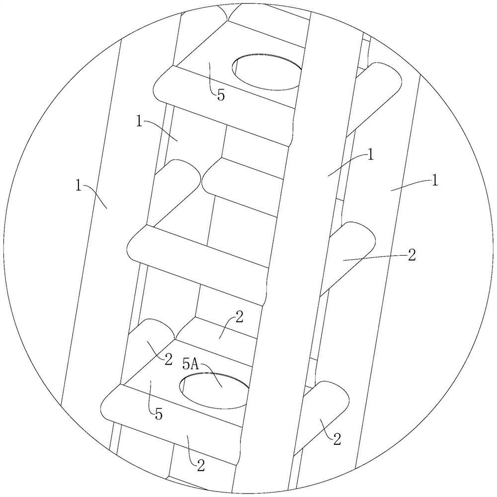
[0048] A steel pipe concrete bridge tower, such as Figure 1-10 , including several splicing segments, the splicing segment includes several steel pipes-1 and at least one consolidation unit located on the steel pipe-1, the steel pipe-1 is filled with concrete, and the consolidation unit is used to connect all the steel pipes-1 as a whole, ensuring The overall stability of the steel tube concrete bridge tower structure, the consolidation unit includes a number of steel pipes 2, the steel pipe 2 2 is connected to two adjacent steel pipes 1 along the circumferential direction of the bridge tower, and the steel pipe 2 2 is used as a web member, which can resist bending by itself The ability to transmit the unbalanced axial force of two adjacent steel pipes-1; two adjacent consolidation units are arranged at intervals along the longitudinal direction of the bridge tower, and all spliced ​​segments are connected through the butt joint of steel pipe-1.

[0049] In this embodiment, t...

Embodiment 2

[0052] Based on Example 1, as a specific implementation, such as figure 2 , image 3 , the pylon also includes a transverse diaphragm 5 adjoining all steel pipes 2 in a single consolidation unit. The arrangement of the diaphragm 5 is mainly used to improve the torsion resistance and other performances of the bridge tower structure, further strengthening the structural stability. In this embodiment, among all the consolidation units, it is preferable that the transverse diaphragm 5 is arranged longitudinally by one consolidation unit along the bridge tower, so as to ensure that the bridge tower structure has sufficient bending resistance, torsional strength and compressive bearing capacity, saving The amount of steel is used, and the structure is beautiful.

[0053] Further, a manhole 5A is provided in the center of the transverse partition 5, which is convenient for maintenance personnel to pass through.

Embodiment 3

[0055] Based on Example 1, as a specific implementation, such as Figure 4-Figure 7 , the bridge tower also includes a steel pipe 3 3, and the steel pipe 3 3 connects two adjacent steel pipes 2 2 in a single consolidation unit. The arrangement of the steel pipe three 3 can also be used to improve the torsional performance of the bridge tower structure, and further strengthen the structural stability.

[0056] In this embodiment, among all the consolidation units, the steel pipes 33 are arranged at intervals of one consolidation unit along the longitudinal direction of the bridge tower, so as to save steel consumption under the premise of ensuring that the bridge tower structure has sufficient bending resistance, torsional strength and compressive bearing capacity , beautiful structure. Furthermore, the steel pipe 3 3 is a hollow member, and is light in weight.


PUM


Abstract

The invention relates to the technical field of suspension bridges, in particular to a concrete-filled steel tube bridge tower and a construction method thereof. The tower structurally comprises a plurality of first steel tubes used for restraining concrete and a plurality of consolidation units arranged in the axial direction of the bridge tower, and each consolidation unit comprises a plurality of second steel tubes; the second steel pipes are transversely connected with the two adjacent first steel pipes in the circumferential direction of the bridge tower, the bridge tower structure can be divided into a plurality of splicing sections by cutting the first steel pipes between the two adjacent consolidation units, and each splicing section at least comprises one consolidation unit. According to the concrete-filled steel tube bridge tower structure based on the specific design, the bridge tower is divided into the multiple splicing sections only by cutting along the first steel tube, so that prefabricated transportation and high-distance pouring construction of the bridge tower structure are conveniently achieved, aerial intersecting line welding is avoided, the construction difficulty is lowered, the welding seam quality is easier to guarantee. The construction efficiency is improved, the construction is convenient and fast, and the transportation cost and the construction cost are low.

Description

technical field [0001] The invention relates to the technical field of suspension bridges, in particular to a steel pipe concrete bridge tower and a construction method thereof. Background technique [0002] The main tower of the suspension bridge is the main load-bearing member of the suspension bridge to resist the vertical load, mainly under compression. The main tower of the traditional suspension bridge adopts concrete bridge tower, steel bridge tower and hybrid bridge tower structure; among them, the concrete bridge tower is widely used because of its high bearing capacity, but due to its large self-weight, the bearing capacity under earthquake will be lower instead, and the concrete bridge tower More sand and gravel are needed, the construction cost is high, and the construction period is generally more than one year, which takes a long time; the steel tower has a small weight, which is good for earthquake resistance, but the amount of steel is large and the cost is h...

Claims


Application Information

Patent Timeline
Patent Type & Authority Applications(China)
IPC IPC(8): E01D19/14E01D21/00E01D11/02E01D101/26
CPCE01D19/14E01D21/00E01D11/02E01D2101/268
Inventor 梁健牟廷敏郑旭峰谭邦明王戈范碧琨宋瑞年刘振宇费豪肖雨李畅何娇阳
Owner SICHUAN DEPT OF TRANSPORTATION HIGHWAY PLANNING PROSPECTING & DESIGN RES INST
Learn More