A drive device for a vertical mill

A driving device, vertical mill technology, applied in the direction of transmission, gear transmission, transmission parts, etc., can solve the problems of shortened service life, eccentric rotation of the motor rotor, and the rotor cannot run at full speed, etc., to improve the heat dissipation effect, Effects of stable operating environment

Active Publication Date: 2022-07-05
博远机电(南通)有限公司
View PDF0 Cites 0 Cited by
  • Summary
  • Abstract
  • Description
  • Claims
  • Application Information

AI Technical Summary

Problems solved by technology

The start-up process of the vertical mill is the point with the largest load. The conventional drive device will cause the transmission bearing to be subjected to a huge load during the start-up process, which will damage the drive shaft. On the other hand, the rotor cannot run at full speed during the start-up process. More magnetic loss will be generated, which will increase the heat generation of the motor
The motor rotor inevitably has errors during the machining process. Some motor rotors will have a problem of excessive local density. This problem will cause the motor rotor to be eccentric when it rotates, which will lead to increased vibration during the motor rotation process and shortened service life.

Method used


Image

  • A drive device for a vertical mill
  • A drive device for a vertical mill
  • A drive device for a vertical mill

Examples


Embodiment Construction

[0021] The technical solutions in the embodiments of the present invention will be clearly and completely described below with reference to the accompanying drawings in the embodiments of the present invention. Obviously, the described embodiments are only a part of the embodiments of the present invention, but not all of the embodiments. Based on the embodiments of the present invention, all other embodiments obtained by those of ordinary skill in the art without creative efforts shall fall within the protection scope of the present invention.

[0022] see Figure 1-7 , the present invention provides technical scheme:

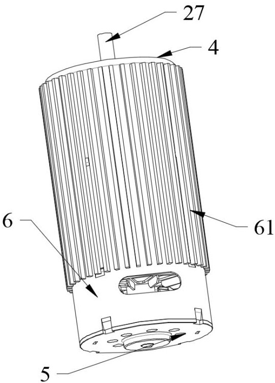
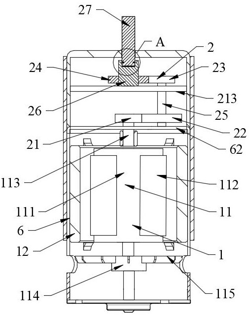
[0023] like figure 1 , 2 As shown, a driving device for a vertical mill includes a motor assembly 1, a reducer assembly 2, a ventilation assembly 3, a front end cover 4, a rear end cover 5, an annular cover 6, a front end cover 4, and a rear end cover 5 They are respectively fastened to both ends of the annular cover 6, the motor assembly 1 and the reducer ...


PUM


Abstract

The invention discloses a driving device for a vertical mill, comprising a motor assembly, a reducer assembly, a ventilation assembly, a front end cover, a rear end cover, and an annular cover. The motor assembly and the reducer assembly are arranged in the cavity in the middle of the annular cover, and the ventilation assembly is arranged in the inner wall of the annular cover. It is divided into a first cavity and a second cavity, the reducer assembly is installed inside the first cavity, and the motor assembly is installed inside the second cavity. The correction component of the present invention corrects the eccentricity caused by the uneven density of the rotating iron core through the centrifugal force difference, which greatly reduces the rotation loss of the device and improves the energy conversion rate. The speed reducer assembly of the present invention is started by reducing the speed of the vertical mill, so as to avoid excessive load on the transmission bearing and prolong the service life of the equipment.

Description

technical field [0001] The invention relates to the technical field of driving devices, in particular to a driving device for a vertical mill. Background technique [0002] Due to the large starting load of vertical mills, the drive device has always been the core component of the equipment. The traditional vertical mill drive device is generally driven by a three-phase asynchronous motor with a planetary gear reducer. The orthogonal shaft bevel gear pair of the asynchronous motor gearbox not only needs to complete the torque transmission, but also complete the torque amplification, and at the same time complete the torque reversal, which is the biggest "pain point" of the conventional drive system. Faults such as pitting corrosion and even shaft breakage are inevitable. The starting process of the vertical mill is the maximum load point. The conventional driving device will cause the transmission bearing to be subjected to a great load during the starting process, thereby...

Claims


Application Information

Patent Timeline
Patent Type & Authority Patents(China)
IPC IPC(8): F16H1/22F16H57/023F16H57/04B02C23/00
CPCF16H1/22F16H57/023F16H57/0416B02C23/00
Inventor 张永生杜洪伟邹建华张爽闫丽利
Owner 博远机电(南通)有限公司
Why Eureka
Try Eureka