Comprehensive well site measurement and control cabinet

A technology of comprehensive measurement and control and measurement and control cabinets, which is applied in the direction of program control, comprehensive factory control, electrical program control, etc., can solve problems such as large differences in data bandwidth, upper-layer network burden, and impact on communication quality, so as to achieve reasonable internal space layout and improve The effect of improving service life and reliability and communication quality

Inactive Publication Date: 2015-07-08
蒋辉
View PDF5 Cites 5 Cited by
  • Summary
  • Abstract
  • Description
  • Claims
  • Application Information

AI Technical Summary

Problems solved by technology

[0002] At present, in the field of domestic crude oil exploitation, RTU or PLC is generally used as industrial control components to measure and control various parameters of oil wells. In actual use, RTU or PLC is usually placed in oil well measurement and control cabinets. From the perspective of application, since the oil wells are located in the wilderness with harsh environment, and most of them are scattered, these objective factors are a severe test for the network communication system of the entire oil field. From the well site to the booster station, and then from the booster station to the operation area, the data bandwidth required for transmission between each level varies greatly, and will vary greatly according to the actual situation on site. Different equipment, but most of the existing common measurement and control cabinets use the same type of equipment, which causes a great burden on the upper network, causing the network to often freeze or even disconnect, seriously affecting the communication quality

Method used


Image

  • Comprehensive well site measurement and control cabinet
  • Comprehensive well site measurement and control cabinet
  • Comprehensive well site measurement and control cabinet

Examples


Embodiment Construction

[0019] The present invention will be described in detail below in conjunction with the accompanying drawings and specific embodiments.

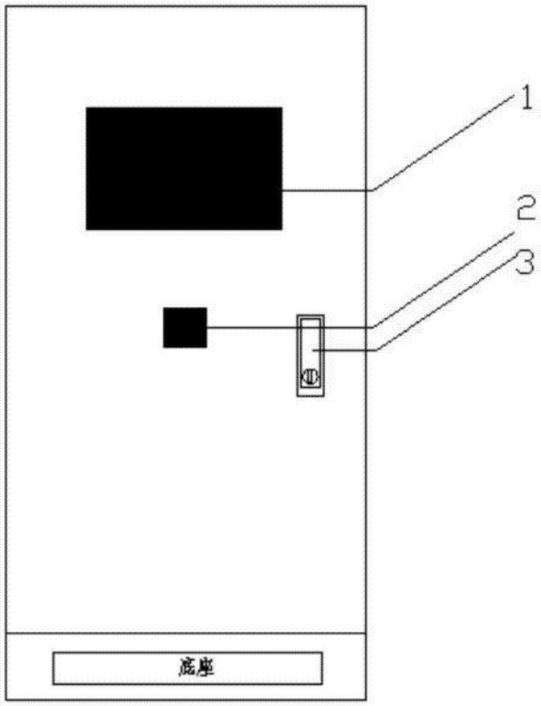
[0020] see figure 1 , a well site comprehensive measurement and control cabinet, the front of the cabinet outer body has a cabinet door, and a 7inch touch screen 1 is arranged on the cabinet door, which can display various parameters of the well site, monitor and capture records, and at the same time monitor the RTU, PLC Parameters can be modified on site (encryption authority is set), and the operation status of each equipment in the cabinet and the ambient temperature in the cabinet can be displayed in real time; the cabinet door is equipped with a local and remote switch 2, which can start and stop the range hood locally or remotely; the cabinet door There is an anti-theft safety lock 3 on the top, using a special key, and the key hole has a lock cover, which can realize a simple anti-theft function; the joint between the cabinet door and ...


PUM


Abstract

The invention relates to a comprehensive well site measurement and control cabinet. As an oil well is located in a wild and desolate site with a harsh environment, objective factors form a severe test on a network communication system of an oil field. The invention aims at providing the comprehensive well site measurement and control cabinet. A communication unit and a measurement and control unit process signals detected by devices such as an oil field sensor and a motor, and the signals are finally transmitted to a man-machine interaction interface of an upper computer in a TCP/IP, Modbus or other form; a video monitoring and communication unit is provided with a McWill MEM136 communication module, the module has a flexible network architecture and is a communication mode mainly promoted by the measurement and control cabinet; the measurement and control cabinet can be compatible with various communication protocols according to actual conditions; and the measurement and control unit is provided with RTU and PLC control modules and supports Modbus-RTU and TCP/IP protocols. The comprehensive well site measurement and control cabinet can be compatible with various communication protocols, invasion of natural disasters such as thunder and lightning, rain and snow, sand wind and the like can be resisted, and the RTU/PLC is in a relatively-stable operation environment; the measurement and control cabinet can resist theft, damage and explosion; and the inner space is reasonably arranged, and late maintenance and expansion are facilitated.

Description

technical field [0001] The invention relates to the field of crude oil exploitation, in particular to a well site comprehensive measurement and control cabinet. Background technique [0002] At present, in the field of domestic crude oil exploitation, RTU or PLC is generally used as industrial control components to measure and control various parameters of oil wells. In actual use, RTU or PLC is usually placed in oil well measurement and control cabinets. From the perspective of application, since the oil wells are located in the wilderness with harsh environment, and most of them are scattered, these objective factors are a severe test for the network communication system of the entire oil field. From the well site to the booster station, and then from the booster station to the operation area, the data bandwidth required for transmission between each level varies greatly, and will vary greatly according to the actual situation on site. Different equipment, but most of the...

Claims


Application Information

Patent Timeline
Patent Type & Authority Applications(China)
IPC IPC(8): G05B19/418H05K5/06
CPCG05B19/05G05B2219/25268
Inventor 孙健李海袁先义
Owner 蒋辉
Why Eureka
Try Eureka