Rod position system detection platform

A detection platform and rod position technology, applied in nuclear power generation, climate sustainability, nuclear reaction control, etc., can solve the problems of lack, complex rod position system function and structure, etc. The degree of knowledge and the effect of improving detection efficiency

Pending Publication Date: 2022-02-18
STATE NUCLEAR POWER AUTOMATION SYST ENGCO
View PDF0 Cites 1 Cited by
  • Summary
  • Abstract
  • Description
  • Claims
  • Application Information

AI Technical Summary

Problems solved by technology

[0004] The technical problem to be solved by the present invention is to provide a rod position system detection platform in order to overcome the defects in the prior art that the rod position system is very complex in function and structure and lacks a visual and intelligent simulation and detection system or equipment

Method used


Image

  • Rod position system detection platform
  • Rod position system detection platform
  • Rod position system detection platform

Examples


Embodiment 1

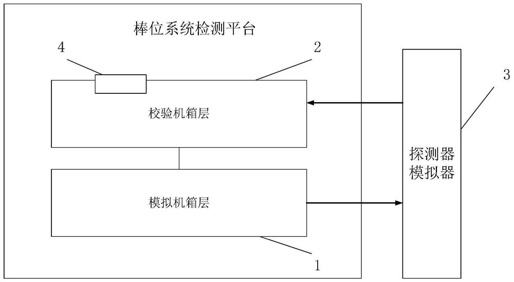
[0052] Please refer to figure 1 , which is a schematic structural diagram of the detection platform of the rod position system in this embodiment. Specifically, such as figure 1 As shown, the rod position system detection platform is connected to the detector simulator 3 in communication, and the rod position system detection platform includes a verification chassis layer 2 and a rod position logic simulation chassis layer 1 . The detector simulator 3 can simulate the on-site control rod position detector through the internal circuit, and generate corresponding rod position measurement signals, which can be used to realize the channel inspection and fault location diagnosis of the rod position system.

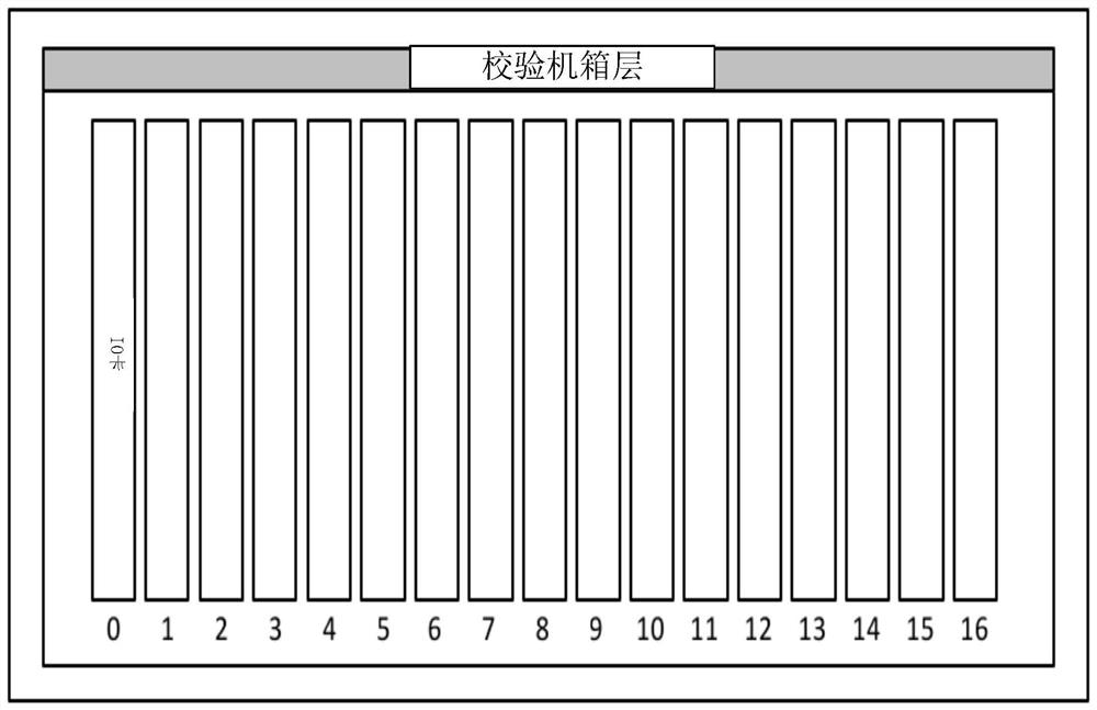
[0053] The verification chassis layer 2 includes a verification interface 4; the verification interface 4 is used to connect the components under test of the rod position system. The verification chassis layer is used to simulate the data acquisition cabinet of the rod positi...

Embodiment 2

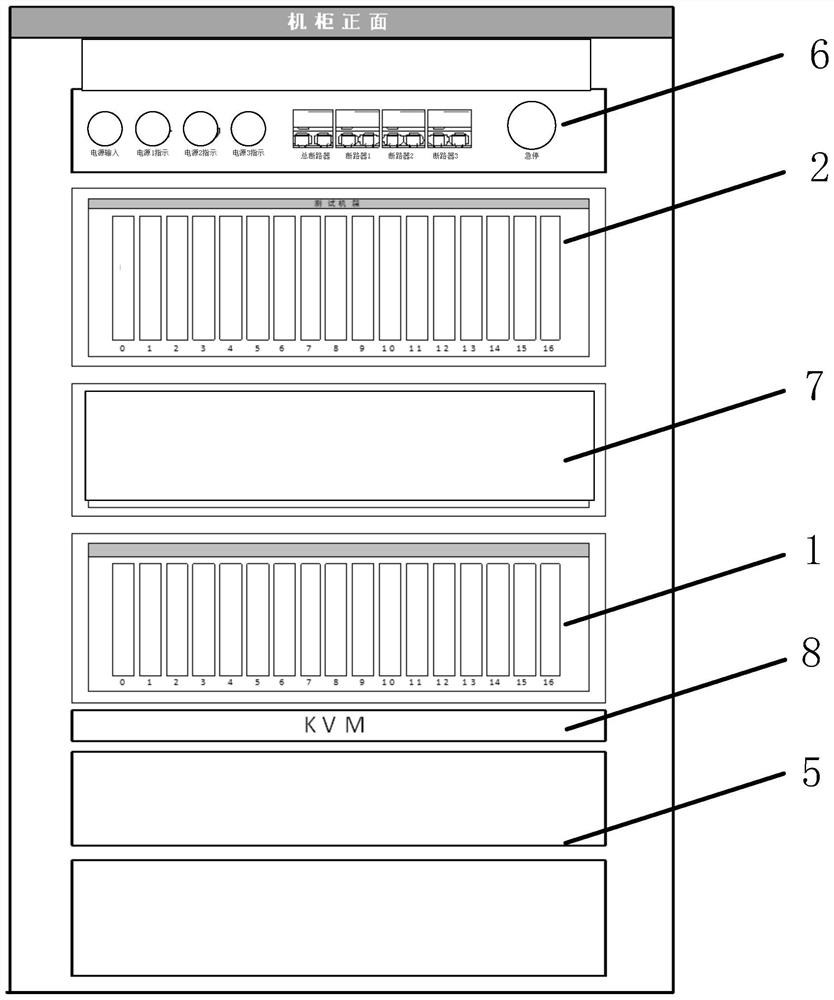
[0058] Such as figure 2 As shown, the rod position system detection platform of this embodiment is a further improvement to Embodiment 1, specifically:

[0059] In this embodiment, the rod position system testing platform further includes a DCS control cabinet; the verification chassis layer 2 and the rod position logic simulation chassis layer 1 are arranged in the DCS control cabinet.

[0060] Specifically, the rod position system detection platform uses DCS cabinet as the hardware environment, LABVIEW (a program development environment) as the development platform, and MySQL (a relational database management system) as the database server, mainly realizing data storage, management, display, etc. Features. It has security protection function and can set a login password to ensure that only legally authorized users can operate the device.

[0061] In an optional implementation manner, the component to be tested includes a coding card to be tested, an IO card to be tested, ...


PUM


Abstract

The invention discloses a rod position system detection platform. The rod position system detection platform is in communication connection with a detector simulator, and the rod position system detection platform comprises a verification case layer and a rod position logic simulation case layer, wherein the verification case layer comprises a verification interface; the verification interface is used for connecting a to-be-tested assembly of the rod position system; the rod position logic simulation case layer is used for generating a rod position signal and sending the rod position signal to the detector simulator; the verification case layer is used for receiving simulated rod position information generated by the detector simulator based on the rod position signal and sending the simulated rod position information to the to-be-tested assembly; and the rod position logic simulation case layer is also used for receiving a function processing result of the to-be-tested component and comparing the function processing result with a preset reference result to output a detection result. According to the rod position system detection platform, function simulation of the rod position system is achieved, the to-be-detected assembly is connected into the verification case layer and detected in the simulated rod position system, the detection efficiency is improved, and certain technical support is provided for overhaul.

Description

technical field [0001] The invention relates to the technical field of nuclear power system simulation and detection, in particular to a rod position system detection platform. Background technique [0002] The main function of the digital rod position indicating system is to detect the position of the control rods in the core. The digital rod position indicating system is called the rod position system for short. The rod position system includes data acquisition cabinets, rod position logic cabinets, rod drop test cabinets, rod position detectors and other equipment. The rod position system is used to monitor the position of the control rods when they are inserted or lifted in the reactor core, and the system also includes the rod drop test subsystem to measure the rod drop time. The rod position system detects the position of each bundle of control rods in the reactor core, collects and processes all rod position detector signals, sends out rod position information and i...

Claims


Application Information

Patent Timeline
Patent Type & Authority Applications(China)
IPC IPC(8): G21C7/36G21C17/00
CPCG21C7/36G21C17/001Y02E30/30
Inventor 王冠峰张静超刘爱青杨帆蔡振东薛家琚王聪吴庆双曹婷兰茜李江华
Owner STATE NUCLEAR POWER AUTOMATION SYST ENGCO
Why Eureka
Try Eureka