Check patentability & draft patents in minutes with Patsnap Eureka AI!

Self-locking control handle structure

A technology of control handle and self-locking structure, which is applied in the direction of control mechanism, aircraft braking arrangement, etc., can solve the problems of small control force and small idle travel, so as to prevent misoperation, improve corrosion, and improve the service life of the structure Effect

Pending Publication Date: 2022-02-25
贵州新安航空机械有限责任公司
View PDF0 Cites 0 Cited by
  • Summary
  • Abstract
  • Description
  • Claims
  • Application Information

AI Technical Summary

Problems solved by technology

[0004] (1) Although the structure of the push-pull control handle has a small idle stroke, the control force is small during emergency braking;

Method used


Image

  • Self-locking control handle structure
  • Self-locking control handle structure
  • Self-locking control handle structure

Examples


Embodiment Construction

[0034] Below, the present invention will be further described in conjunction with the accompanying drawings and specific implementation methods. It should be noted that, under the premise of not conflicting, the various embodiments described below or the technical features can be combined arbitrarily to form new embodiments. .

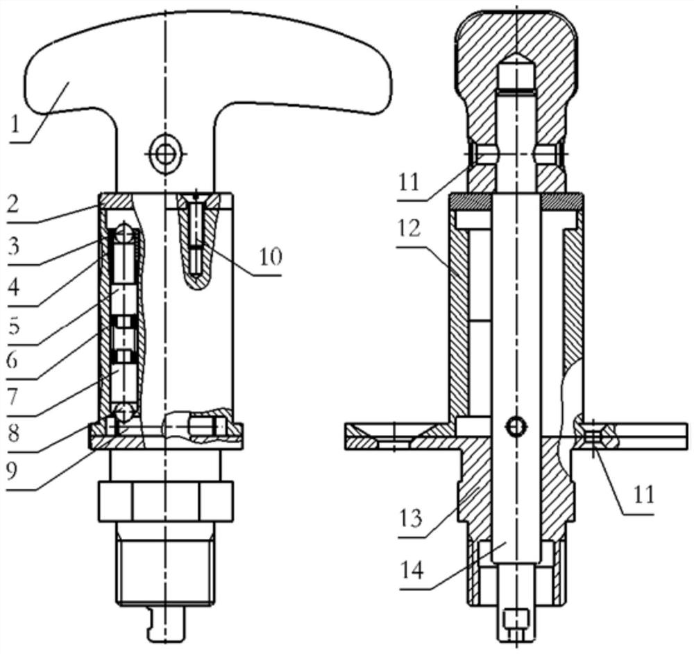
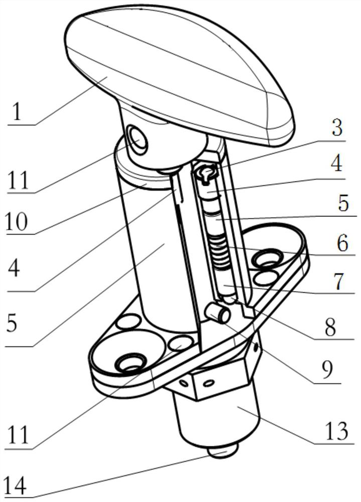
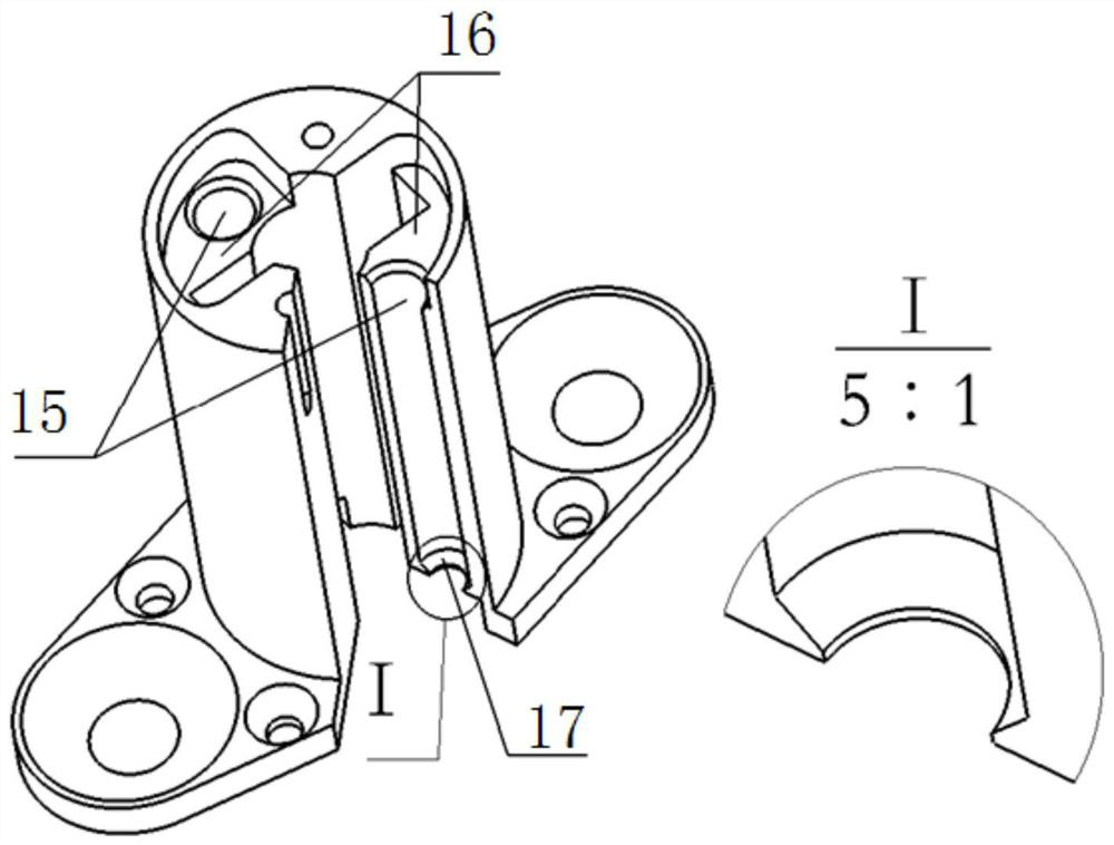
[0035] like figure 1 , figure 2 Shown is a self-locking control handle structure, which includes a fixed sleeve assembly, a handle 1, an end cover 2, a first steel ball 3, a screw plug 4, a push rod 5, a spring 6, a spring seat 7, a second steel Ball 8, cylindrical pin 9, countersunk head rivet 10, countersunk head screw 11, upper fixing sleeve 12, lower fixing sleeve 13, pull rod 14 are formed, and fixing sleeve assembly includes such as image 3 The upper fixing sleeve 12 shown and as Figure 7 In the lower fixed sleeve 13 shown, the control handle 1 adopts a T-shaped handle; the fixed sleeve assembly is provided with a screw plug 4, a push rod 5...


PUM


Abstract

The invention discloses a self-locking control handle structure which comprises a T-shaped handle, a pull rod, a fixing sleeve assembly and a self-locking structure, one end of the pull rod is connected with the T-shaped handle, the other end of the pull rod penetrates through the fixing sleeve assembly to be connected with a steel cable or a hydraulic valve, and a cylindrical pin is arranged in the middle of the pull rod; the fixing sleeve assembly comprises an upper fixing sleeve and a lower fixing sleeve, and the upper fixing sleeve and the lower fixing sleeve can be connected together through a sunk screw; and an end cover is arranged at the upper end of the upper fixing sleeve. The self-locking control handle structure can realize a self-locking function for a specific aircraft in a working state and a non-working state.

Description

technical field [0001] The invention relates to the technical field of emergency control systems, in particular to a self-locking control handle structure. Background technique [0002] The typical control forms of my country's aircraft emergency operating systems include mechanical emergency operating systems and electronically controlled emergency braking systems, both of which are different. The typical electronically controlled emergency brake is controlled by the brake pedal; the typical mechanical emergency control system uses the cockpit handle to pull the cable to control the emergency valve to implement emergency control. For the design of the aircraft emergency system, the mechanical emergency control system can be Ensure high system reliability and low cost. The mechanical operation can implement the operation action according to the operation experience, which realizes the ergonomic design. [0003] At present, the mechanical emergency control structure in our ...

Claims


Application Information

Patent Timeline
IPC IPC(8): B64C25/44
CPCB64C25/44
Inventor 王新中詹永鹏王洋
Owner 贵州新安航空机械有限责任公司
Features
  • R&D
  • Intellectual Property
  • Life Sciences
  • Materials
  • Tech Scout
  • Unparalleled Data Quality
  • Higher Quality Content
  • 60% Fewer Hallucinations
Learn More