
Furnace shell of automatic continuous tempering furnace

A technology of tempering furnace and furnace shell, which is applied in the field of automatic continuous tempering furnace shell, which can solve the problems of increased risk and easy bending, and achieve the effect of improving heat preservation effect and stable placement

Pending Publication Date: 2022-02-25
NANJING ZHUO LEI FURNACE SCI & TECH CO LTD
View PDF0 Cites 0 Cited by
  • Summary
  • Abstract
  • Description
  • Claims
  • Application Information

AI Technical Summary

Problems solved by technology

The existing tempering furnace shell is mostly connected and tempered by means of a conveyor belt. The processing material is heavy, easy to bend, and when heated unevenly, the material of a furnace is likely to produce different effects. , using fan auxiliary heat, when the furnace is turned on, an instant heat wave is generated, which greatly increases the danger to the staff during operation. Therefore, we propose an automatic continuous tempering furnace shell

Method used


Image

  • Furnace shell of automatic continuous tempering furnace
  • Furnace shell of automatic continuous tempering furnace
  • Furnace shell of automatic continuous tempering furnace

Examples


Embodiment Construction

[0020] In order to make the technical means, creative features, goals and effects achieved by the present invention easy to understand, the present invention will be further described below in conjunction with specific embodiments.

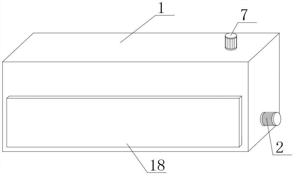
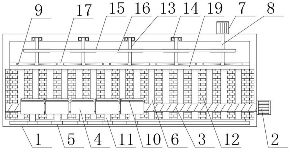
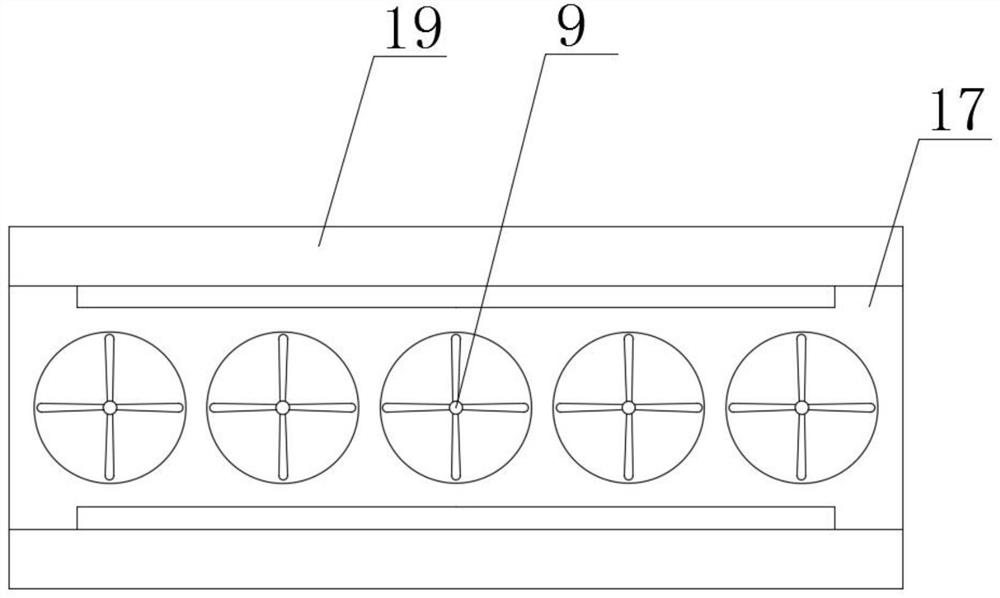
[0021] Such as Figure 1-4 As shown, an automatic continuous tempering furnace shell, including a furnace shell 1, the outer surface of the right side of the furnace shell 1 is provided with a No. 1 motor 2, the No. The left outer surface of the motor 2 is provided with a No. 1 rotary rod 3 that runs through the interior of the furnace shell 1. There are multiple sets of sliders 4 on the outer surface of the No. 1 rotary rod 3. The bottom of the slider 4 is located at the bottom of the furnace shell 1. Sliding plate 5 is arranged, the both sides of slide block 4 and the outside of collecting pipe 19 are all provided with collecting pipe 19, the outer surface of the bottom of collecting pipe 19 and the inside of furnace shell 1 are provided with mu...


PUM


Abstract

The invention discloses an automatic continuous tempering furnace shell which comprises a furnace shell body, a first motor is arranged on the outer surface of the right side of the furnace shell body, a first rotating rod penetrating through the interior of the furnace shell body is arranged on the outer surface of the left side of the first motor, and multiple sets of sliding blocks are arranged on the outer surface of the outer side of the first rotating rod; a sliding plate is arranged at the bottom of the sliding block and located at the bottom of the furnace shell, line concentration pipes are arranged on the two sides of the sliding block and located in the furnace shell, multiple sets of heating rods are arranged on the outer surfaces of the bottoms of the line concentration pipes and located in the furnace shell, and a second motor is arranged on the right side of the outer surface of the top of the furnace shell; a second rotating rod penetrating through the top of the furnace shell is arranged at the bottom of the second motor, and a fan is arranged at the bottom of the second rotating rod. According to the furnace shell of the automatic continuous tempering furnace, the mode that the sliding blocks support the machined part for tempering is adopted, the moving stability of the machined part in the furnace shell is improved, the structure is compact, and the safety of the furnace shell is improved.

Description

technical field [0001] The invention relates to the technical field, in particular to an automatic continuous tempering furnace shell. Background technique [0002] The tempering furnace is used for tempering general metal parts in air and quenching, annealing and aging heat treatment for aluminum alloy die-casting parts, pistons, aluminum plates and other light alloy parts. The shell is welded by steel plate and section steel, and the trolley is welded by section steel and steel plate. The trolley can reduce heat radiation and convection loss through soft contact with the furnace lining and sand sealing mechanism, and effectively ensure the sealing of the furnace body. The existing tempering furnace shell is mostly connected and tempered by means of a conveyor belt. The processing material is heavy, easy to bend, and when heated unevenly, the material of a furnace is likely to produce different effects. , using fan auxiliary heat, when the furnace is turned on, an instant ...

Claims


Application Information

Patent Timeline
Patent Type & Authority Applications(China)
IPC IPC(8): C21D9/00
CPCC21D9/0006C21D9/0018
Inventor 董福根
Owner NANJING ZHUO LEI FURNACE SCI & TECH CO LTD
Learn More