Highway tamping device for highway engineering
A tamping device and road technology, which is applied in the direction of roads, roads, road surface cleaning, etc., can solve the problems of small tamping area, low work efficiency, inconvenient operation, etc., to improve practicability, improve work efficiency, and increase the effect area effect
- Summary
- Abstract
- Description
- Claims
- Application Information
AI Technical Summary
Problems solved by technology
Method used
Image

Examples
Embodiment 1
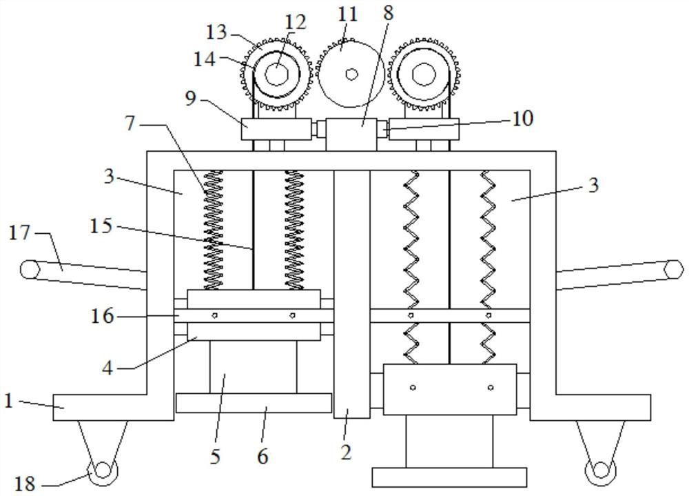
[0028] Such as figure 1 , Image 6 As shown, the present invention provides a technical solution, a road compacting device for road engineering, comprising a mounting frame 1, the left and right side walls of the mounting frame 1 are provided with hand push rods 17, and the bottom surface of the mounting frame 1 is provided with The four wheels 18 distributed in a rectangle are convenient for construction workers to quickly move the device to a designated position. The center of the mounting frame 1 is fixedly connected with a vertical plate 2, wherein the space between the vertical plate 2 and the left side wall of the mounting frame 1, and the space formed by the vertical plate 2 and the right side wall of the mounting frame 1 is set as the working chamber 3, That is to say, there are two working chambers 3, the front and rear sides and the lower side of the working chamber 3 are all opened, and the inside of the working chamber 3 is slid to be provided with a tamping piece...
Embodiment 2
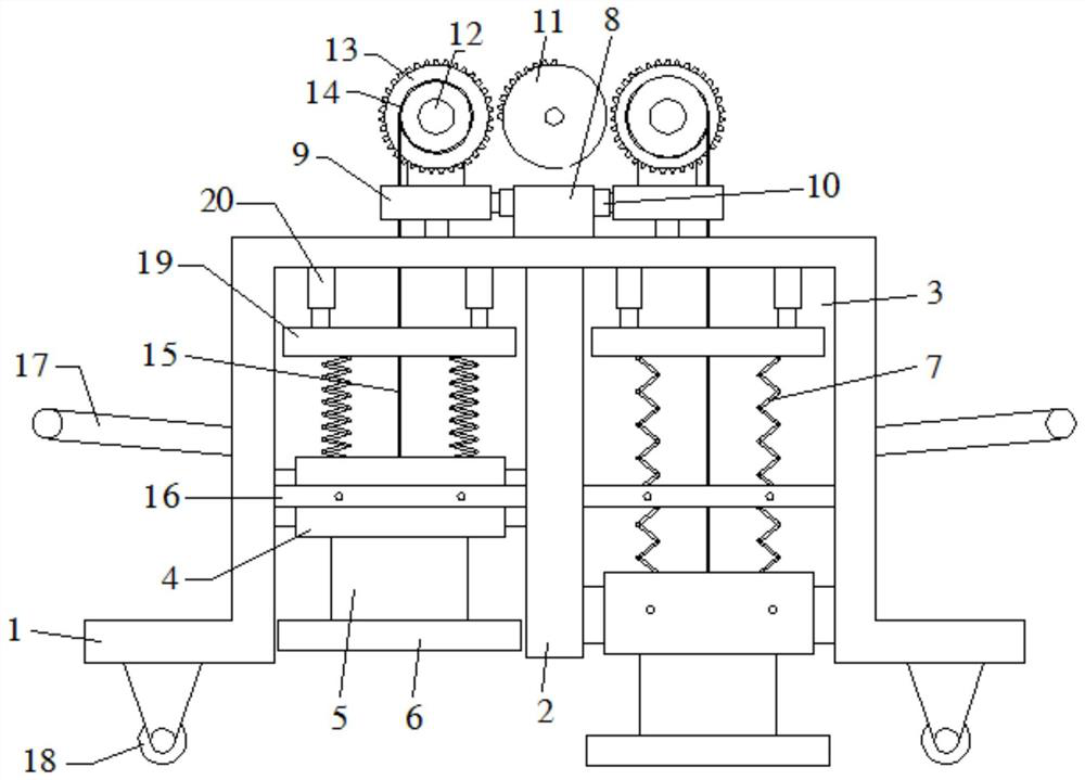
[0034] Different from Example 1, as figure 2 , Image 6As shown, the inside of the working chamber 3 is also provided with an adjustment plate 19, the adjustment plate 19 is located above the weight block 4, a hydraulic rod 20 is arranged between the adjustment plate 19 and the upper side wall of the mounting frame 1, and the spring 7 is fixedly connected to the Between the adjustment plate 19 and the weight block 4 . By changing the position of the adjusting plate 19, the force of the tamping block 6 on the road surface can be changed, which ensures the tamping quality of the device on the road surface, and avoids the situation that the road surface is damaged or not dense due to improper tamping strength. Before working, adjust the hydraulic lever 20 to move the adjustment plate 19 downward, and accordingly the initial position of the compacting block 6 will move downward for a certain distance, that is, the distance between the compacting block 6 and the road surface will...
Embodiment 3
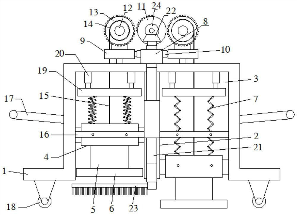
[0036] The difference from the above-mentioned embodiment is that, if Figure 3-6 As shown, the center of the fixed seat 8 and the vertical plate 9 is provided with a through groove, and the through groove on the fixed seat 8 corresponds up and down with the through groove on the vertical plate 9; the through groove is provided with a bearing, and the bearing is fixedly interspersed Control rod 21 is arranged, and control rod 21 can rotate freely, and the top of control rod 21 is fixedly connected with first bevel gear 22 by upper telescopic rod, and first bevel gear 22 is positioned at the top of fixed seat 8, can be adjusted by upper telescopic rod, come Realize whether the first bevel gear 22 and the second bevel gear 24 mesh, and then determine whether the control rod 21 rotates, the bottom end of the control rod 21 is movably inserted with a cleaning brush through the lower telescopic rod, and the cleaning brush 23 is positioned at the bottom of the vertical plate. Can ma...
PUM
 Abstract
Description
Claims
Application Information
 - R&D
- Intellectual Property
- Life Sciences
- Materials
- Tech Scout
- Unparalleled Data Quality
- Higher Quality Content
- 60% Fewer Hallucinations
Browse by: Latest US Patents, China's latest patents, Technical Efficacy Thesaurus, Application Domain, Technology Topic, Popular Technical Reports.
© 2025 PatSnap. All rights reserved.Legal|Privacy policy|Modern Slavery Act Transparency Statement|Sitemap|About US| Contact US: help@patsnap.com