Wide-angle projection lens for optical waveguide AR lens detection

A projection lens and optical waveguide technology, applied in the field of lenses, can solve problems such as difficulty in correcting diaphragm aberrations, and achieve the effects of improving coincidence, improving energy utilization, and avoiding lens interference.

Active Publication Date: 2022-02-25
MOONLIGHT (NANJING) INSTR CO LTD
View PDF12 Cites 3 Cited by
  • Summary
  • Abstract
  • Description
  • Claims
  • Application Information

AI Technical Summary

Problems solved by technology

[0004] Purpose of the invention: In view of the problem that the aperture aberration of the wide-angle lens is difficult to correct, the present invention provides a wide-angle projection lens for optical waveguide AR lens detection

Method used


Image

  • Wide-angle projection lens for optical waveguide AR lens detection
  • Wide-angle projection lens for optical waveguide AR lens detection
  • Wide-angle projection lens for optical waveguide AR lens detection

Examples


Embodiment 1

[0049] Table 1 Technical Indicators of Embodiment 1

[0050]

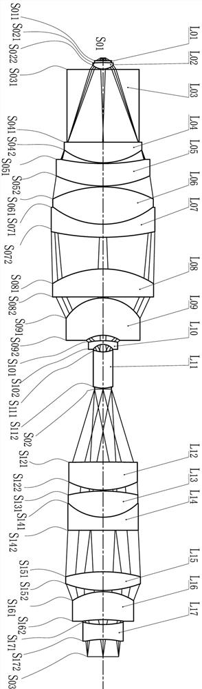
[0051] Such as figure 1 As shown, a wide-angle projection lens for optical waveguide AR lens detection, including 16 lenses and 1 prism, from top to bottom (ie figure 1 Shown in the direction from the virtual diaphragm S01 to the reticle surface S03) includes: the first lens L01, the second lens L02, the deflection prism L03, the third lens L04, the fourth lens L05, the fifth lens L06, the sixth lens Lens L07, seventh lens L08, eighth lens L09, ninth lens L10, tenth lens L11, eleventh lens L12, twelfth lens L13, thirteenth lens L14, fourteenth lens L15, fifteenth lens The parameters of the lens L16 and the sixteenth lens L17, 16 lenses and a prism are shown in Table 2, the first column in Table 2 gives the lens number (that is, the number of the 16 lenses and 1 prism), and the second column gives The number of the upper and lower surfaces of the lens (that is, the number of the upper and lower surfaces of 16 l...

Embodiment 2

[0084] Table 3 Technical indicators of embodiment two

[0085]

[0086] Such as Figure 6 As shown, the projection lens includes 12 lenses and 1 folding prism, from top to bottom (ie Figure 6 (shown in the direction from the virtual diaphragm S01 to the reticle surface S03) includes: folding prism L03, fourth lens L05, fifth lens L06, seventh lens L08, eighth lens L09, ninth lens L10, Tenth lens L11, eleventh lens L12, twelfth lens L13, seventeenth lens L18, fourteenth lens L15, fifteenth lens L16 and sixteenth lens L17, 12 lenses and 1 folding prism The parameter table is shown in Table 4. The first column in Table 4 gives the lens number, and the second column gives the number of the upper and lower surfaces of the lens, where S01 indicates the virtual diaphragm of the projection lens, S03 indicates the reticle surface, and the third column The surface type indicates that the surface of the lens is spherical or flat. The fourth column indicates the degree of curvature ...


PUM


Abstract

The invention discloses a wide-angle projection lens for optical waveguide AR lens detection, which sequentially comprises a front lens group, a diaphragm opening and a rear lens group from top to bottom. The front lens group projects the diaphragm opening to the foremost end of the lens to form a virtual diaphragm; the front lens group sequentially comprises a turning prism, a fourth lens, a fifth lens, a seventh lens, an eighth lens, a ninth lens and a tenth lens from top to bottom; and the multiplying power beta of the front lens group is more than 1.8 and less than 3.0. According to the wide-angle projection lens, the entity diaphragm in the lens is led out of the lens to become a virtual diaphragm, the contact ratio of exit pupils is smaller than 0.1 mm through correction of diaphragm aberration, the exit pupils are overlapped with the diaphragm of AR glasses to be measured, subject matter of the same size can be provided for different view fields, and the coupling energy utilization rate is improved; and meanwhile, the physical interference of the projection lens and the receiving lens in the transverse dimension during the same-side detection of the large-angle object to be detected is solved.

Description

technical field [0001] The invention relates to lens technology, in particular to a wide-angle projection lens used for optical waveguide AR lens detection. Background technique [0002] The optical waveguide can achieve a smaller volume and is favored by mainstream AR optical display equipment manufacturers, and the field of view angle of the optical waveguide is promoted to 90 degrees, 120 degrees or even 150 degrees. At the same time, with the light weight and miniaturization of the module volume, The distance between the entrance pupil of the optical waveguide and the exit pupil at the near point of the eye box can be shortened to 15~18mm, which brings great challenges to the performance testing of the large-angle optical waveguide during the manufacturing process. When testing, the test pattern is introduced from the entrance pupil, and the test pattern is received by the exit pupil within the eye movement range, respectively, with the help of the projection lens and th...

Claims


Application Information

Patent Timeline
Patent Type & Authority Applications(China)
IPC IPC(8): G02B13/00G02B13/06G02B6/00G02B27/01
CPCG02B13/006G02B13/06G02B6/00G02B27/01G02B2027/0178
Inventor 梁思远何姜季荣周威葛建媛吴昊
Owner MOONLIGHT (NANJING) INSTR CO LTD
Why Eureka
Try Eureka