

Finger vein recognition module and recognition system thereof
A recognition system and finger vein technology, applied in character and pattern recognition, fingerprint/palm print acquisition/organization, medical science, etc., can solve the problems of poor recognition effect, large error, low recognition and input accuracy, etc., to achieve Improve the speed of recognition, reduce the difficulty of recognition, and ensure the integrity of the effect
- Summary
- Abstract
- Description
- Claims
- Application Information
AI Technical Summary
Problems solved by technology
Method used
Image

Examples
Embodiment 1
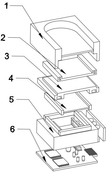
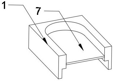
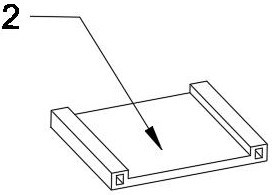
[0030] Embodiment 1: as Figure 1-7 As shown, a finger vein recognition module and its recognition system proposed by the present invention include a finger vein collection tank 1, which is characterized in that the bottom of the finger vein collection tank 1 is provided with a groove, and the inside of the groove is snapped with a Infrared lens 2, the side of the infrared lens 2 away from the finger vein collection tank 1 is fixedly connected with an optical filter 3 through optical glue, the side of the optical filter 3 away from the infrared lens 2 is fixedly connected with a light-emitting element 4, and the light-emitting element 4 is far away from the filter One side of the light sheet 3 is clamped with a sensing unit 5, and the side of the sensing unit 5 away from the light-emitting element 4 is provided with a circuit integration panel 6, and the groove inside the finger vein collection tank 1 is glued with an image acquisition unit 7 through optical glue. A groove is ...
Embodiment 2
[0031] Embodiment 2: as Figure 1-7 As shown, a groove is provided on the side of the induction unit 5 close to the light-emitting element 4, four backlight plates are welded around the top of the groove, a light guide plate 8 is arranged inside the groove, and a part of the groove is far away from the light guide plate 8. The side is provided with a light sensing unit 9, and the side of the light sensing unit 9 away from the light guide plate 8 is fixedly connected with three light guide tubes 11 that penetrate and extend to the outside of the sensing unit 5, and one end of the light guide tube 11 located outside the sensing unit 5 is fixedly connected There is an imaging panel 10, the bottom of the imaging panel 10 is fixedly connected with a cable, the top left side of the circuit integration panel 6 is provided with two processing chips 14, the top of the circuit integration panel 6 is provided with five sets of capacitors 12, and the circuit integration panel 6 A cable po...
Embodiment 3
[0032] Embodiment 3: as Figure 1-7 As shown, the identification process: after the position of the finger pulp is in contact with the contact surface of the image acquisition unit 7 and placed for a period of time, the infrared lens 2 at the bottom of the finger vein collection tank 1 refracts the pulsation frequency of the finger pulp onto the filter 3, The pulsation frequency of the vein is projected onto the light-emitting element 4 through the filter 3, and the pulsation frequency is transmitted to the inside of the sensing unit 5 through the diffusely reflected light of the light-emitting element 4, and then transmitted to the light sensing unit 9 after being refracted by the light guide plate 8 area of the collecting surface, and transmit the pulsation signal to the inside of the imaging panel 10 through the three light guides 11, and image the pulsation frequency through the imaging panel 10, and the imaging information will be output to one of the circuit integration...
PUM
 Abstract
Description
Claims
Application Information