Film die-cutting machine for reducing edge damage
A die-cutting machine and film technology, applied in metal processing and other directions, can solve problems such as damage and difficulty in achieving sheet separation, and achieve the effect of avoiding edge wrinkles and reducing edge damage
- Summary
- Abstract
- Description
- Claims
- Application Information
AI Technical Summary
Problems solved by technology
Method used
Image
Examples
Embodiment 1
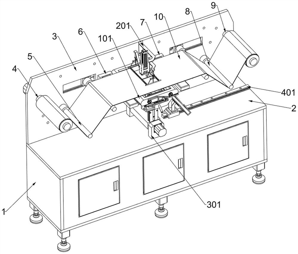
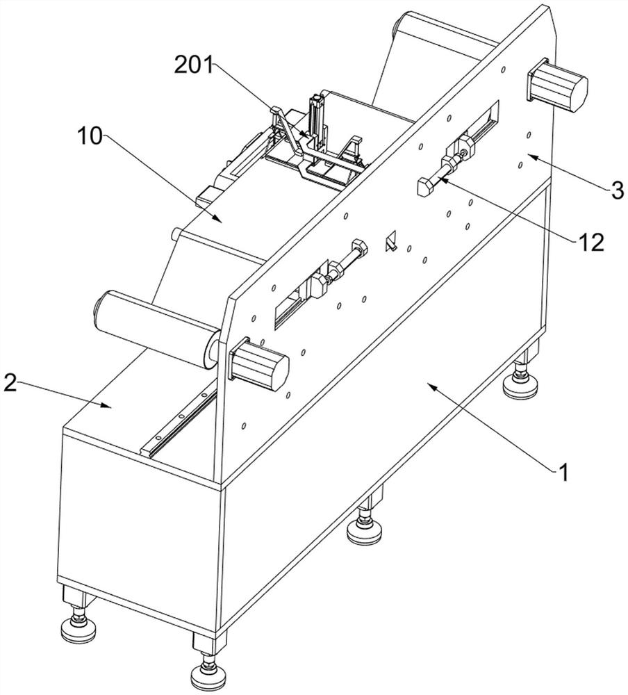
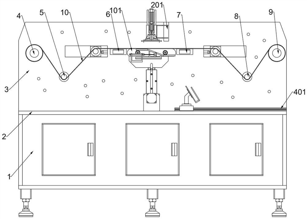
[0034] A film die cutter for reducing edge damage such as Figure 1-5 As shown, it includes a frame 1, a workbench 2, a mounting plate 3, a power unwinding roller 4, a first positioning roller 5, a second positioning roller 8, a power receiving roller 9, a film tensioning system, and a film edge processing system and a die-cutting system; the upper part of the frame 1 is fixedly connected with the workbench 2; the upper surface of the workbench 2 is fixedly connected with the rear part of the installation plate 3; The second positioning roller 8 and the power receiving roller 9, and the power discharging roller 4 and the power receiving roller 9 are located on the same horizontal line, and the first positioning roller 5 and the second positioning roller 8 are located on the same horizontal line; the mounting plate 3 rear portion is connected with A film tensioning system; a die-cutting system is connected to the upper side of the front of the mounting plate 3; a film edge proc...
Embodiment 2
[0037] On the basis of Example 1, such as Figure 1-5 As shown, the film tensioning system includes a first tape release plate 6, a second tape release plate 7, a take-up wheel 11 and a first electric telescopic member 12; the front portion of the mounting plate 3 is fixedly connected with the first tape release plate 6, And the first tape release plate 6 is located on the right side of the first positioning roller 5; the second tape release plate 7 is fixedly connected to the front portion of the mounting plate 3, and the second tape release plate 7 is located on the right side of the first tape release plate 6; The rear part of the mounting plate 3 is fixedly connected with two symmetrical first electric telescopic parts 12; each of the telescopic parts of the two first electric telescopic parts 12 is fixedly connected with a tightening wheel 11; the upper part of the mounting plate 3 is provided with two rectangular grooves, And the two take-up wheels 11 each slide in the c...
Embodiment 3
[0040] On the basis of Example 2, such as figure 1 and 6 As shown in -10, the film edge processing system includes a die-cutting seat 101, an initial cutting assembly 102, an overlapping shaft 103, a dial 104, a flat gear 105, a Z-shaped rack 106, a second moving block 107, and a second straight slide Rail 108, first support frame 109 and third electric telescopic member 1010; die-cut seat 101 is welded on the front of mounting plate 3, and die-cut seat 101 is located between two tightening wheels 11; die-cut seat 101 bottom is fixed There are two initial cutting components 102; the die-cutting seat 101 is internally rotatably connected with two symmetrical overlapping shafts 103; the middle of the outer surface of the two overlapping shafts 103 is fixedly connected with a dial 104; the outer surface of the two overlapping shafts 103 A spur gear 105 is affixed to each of the front parts; a second straight slide rail 108 is affixed to the initial cut assembly 102 in the front;...
PUM
 Abstract
Description
Claims
Application Information
 - R&D
- Intellectual Property
- Life Sciences
- Materials
- Tech Scout
- Unparalleled Data Quality
- Higher Quality Content
- 60% Fewer Hallucinations
Browse by: Latest US Patents, China's latest patents, Technical Efficacy Thesaurus, Application Domain, Technology Topic, Popular Technical Reports.
© 2025 PatSnap. All rights reserved.Legal|Privacy policy|Modern Slavery Act Transparency Statement|Sitemap|About US| Contact US: help@patsnap.com


