Vehicle air conditioning control device

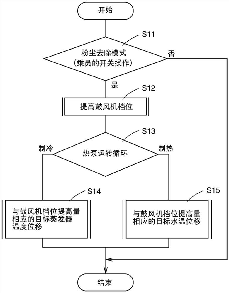
A control device and air-conditioning device technology, which is applied to vehicle parts, transportation and packaging, air handling equipment, etc., can solve the problems of blowing temperature rise and blowing temperature drop, and achieve the purpose of suppressing the decrease of blowing temperature, suppressing the rise of blowing temperature, Comfort stays in good effect

Pending Publication Date: 2022-03-01
TOYOTA JIDOSHA KK
View PDF1 Cites 0 Cited by
  • Summary
  • Abstract
  • Description
  • Claims
  • Application Information

AI Technical Summary

Problems solved by technology

Therefore, in the case of cooling, since the amount of heat that must be taken away to lower the temperature of the wind increases when the air volume increases, the blown temperature rises when the amount of heat taken away from the wind is fixed
In addition, in the case of heating, since the amount of heat that must be applied to increase the temperature of the air increases when the air volume increases, the blowing temperature will decrease when the amount of heat applied to the air is fixed.

Method used


Image

  • Vehicle air conditioning control device
  • Vehicle air conditioning control device
  • Vehicle air conditioning control device

Examples


Embodiment 1

[0053] [Example 1] ( Figure 1 to Figure 5 )

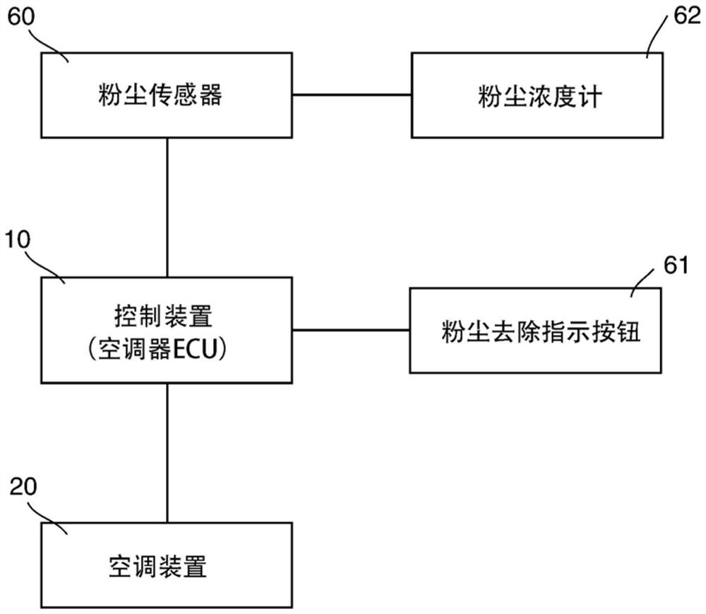
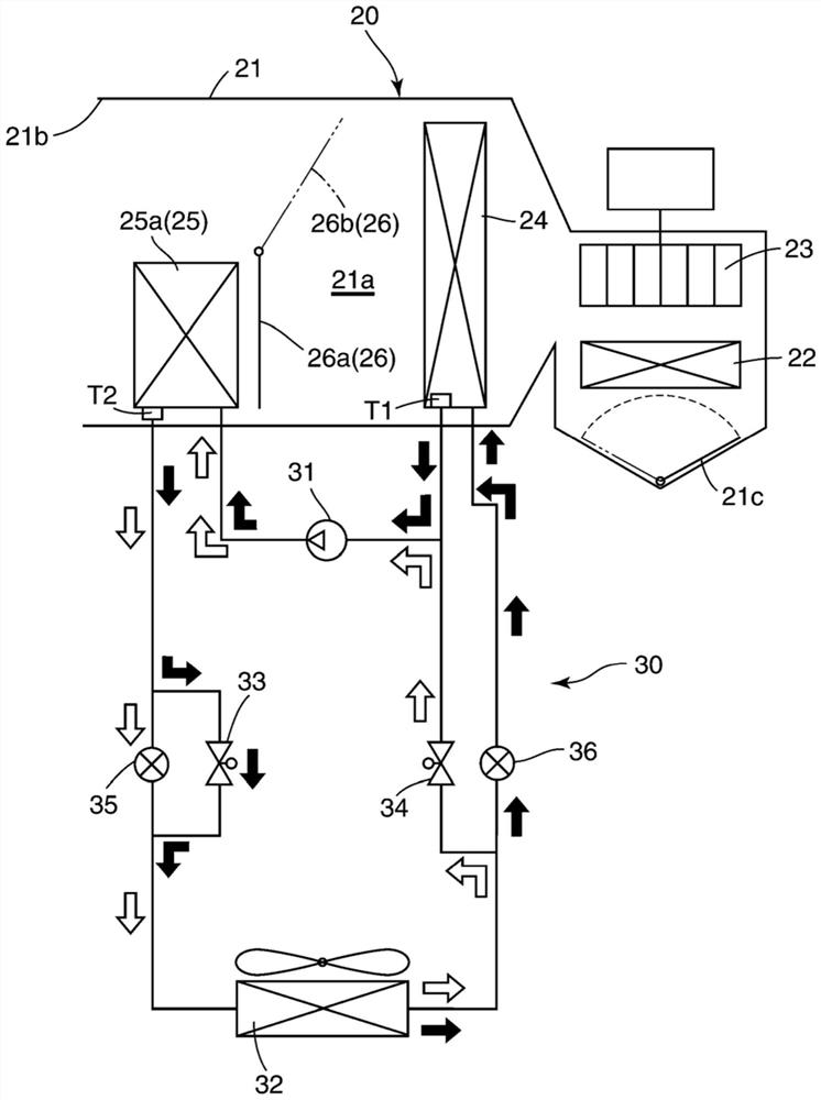
[0054] In Example 1 of the present invention, as figure 2 As shown, the evaporator 24 and the heating unit 25 of the air conditioner 20 constitute a part of a heat pump air conditioner system (heat pump air conditioner cycle) 30 . Furthermore, the heating unit 25 is constituted by an in-vehicle capacitor 25a. The heat pump air conditioner system 30 is a constituent element of the air conditioner 20 .

[0055] Although the heat pump air conditioner system 30 is not particularly limited, it is mainly mounted on a vehicle that does not have an engine (internal combustion engine), that is, an electric vehicle including an EV (Electric Vehicle) and an FCV (Fuel Cell Vehicle). (electric car) on.

[0056] The heat pump air conditioner system 30 includes, in addition to the evaporator 24 and the heating unit 25 (in-cabin capacitor 25a), a compressor 31 for compressing refrigerant (medium), a capacitor 32 outside the cabin, and first ...

Embodiment 2

[0068] [Example 2] ( Image 6 , Figure 7 )

[0069] In Example 2 of the present invention, as Image 6 As shown, the evaporator 24 and the heating part 25 of the air conditioner 20 do not constitute a part of the heat pump air conditioner system. Moreover, the heating part 25 is comprised by the heater core 25b.

[0070]The vehicle not equipped with the heat pump air conditioner system is not particularly limited, and is a vehicle equipped with an engine (internal combustion engine), that is, a gasoline vehicle or an HV (Hybrid Vehicle: hybrid vehicle) vehicle.

[0071] The evaporator 24 is a component of the refrigeration cycle 40 . The refrigeration cycle 40 is a component of the air conditioner 20 . The refrigeration cycle 40 includes a compressor 41 for compressing a refrigerant (medium), a capacitor 42 , and an expansion valve 43 in addition to the evaporator 24 .

[0072] The capacitor 42 is arranged on the downstream side of the compressor 41 in the flow directio...


PUM


Abstract

The invention provides an air conditioner control device for a vehicle. When the dust removal mode is executed while cooling and the air volume is increased, the target temperature of the evaporator is reduced according to the increase in the air volume. Therefore, the heat taken away from the air can be increased according to the increase of the air volume. As a result, an increase in the blowing temperature can be suppressed. On the other hand, when the dust removal mode is executed during heating and the air volume is increased, the target temperature of the medium that exchanges heat with the air through the heating unit is increased in accordance with the increase in the air volume. Therefore, the amount of heat applied to the air can be increased according to the increase of the air volume. Consequently, a decrease in the blowing temperature can be suppressed. According to the above content, when the dust removal mode is used for cooling or heating, the blowing temperature can be prevented from changing according to the increase of the air volume.

Description

technical field [0001] The present invention relates to a vehicle air-conditioning control device for controlling an air-conditioning device for air-conditioning in a vehicle compartment. Background technique [0002] Japanese Patent Application Laid-Open No. 2018-099937 discloses a technique of controlling a blower in order to reduce dust in a vehicle cabin in a dust removal mode so that the air volume blown into the vehicle cabin is increased to the maximum value. [0003] According to the technology disclosed in the above-mentioned gazette, increasing the air volume increases the amount of dust that can be collected by the air conditioner filter per unit time, so that dust can be effectively reduced. [0004] However, the technique disclosed in the above publication has the following problems. [0005] When the air volume is increased, the heat capacity of the air blown into the passenger compartment per unit time increases, so that the blown temperature fluctuates durin...

Claims


Application Information

Patent Timeline
Patent Type & Authority Applications(China)
IPC IPC(8): B60H1/00
CPCB60H1/00892
Inventor 星野优
Owner TOYOTA JIDOSHA KK
Why Eureka
Try Eureka