
Safety auxiliary equipment for steam turbine

An auxiliary equipment and steam turbine technology, applied in the field of steam turbines, can solve the problems of poor damping effect of the base and loose parts of the steam turbine, so as to enhance the shock absorption effect, avoid loose parts and damage, and improve the effect of buffering and shock absorption

Pending Publication Date: 2022-03-01
GRAND NEW POWER
View PDF0 Cites 0 Cited by
  • Summary
  • Abstract
  • Description
  • Claims
  • Application Information

AI Technical Summary

Problems solved by technology

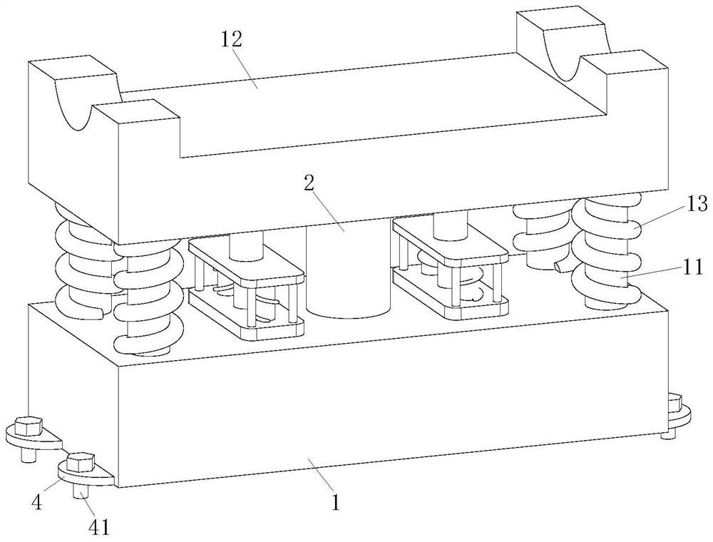
[0005] In order to make up for the deficiencies of the existing technology, the shock absorption effect of the base equipped with the existing steam turbine is poor, and the vibration of the steam turbine will occur during operation. In the case of long-term vibration, the internal parts of the steam turbine will appear loose. Problem, the present invention proposes a steam turbine safety auxiliary equipment

Method used


Image

  • Safety auxiliary equipment for steam turbine
  • Safety auxiliary equipment for steam turbine
  • Safety auxiliary equipment for steam turbine

Examples


Embodiment 1

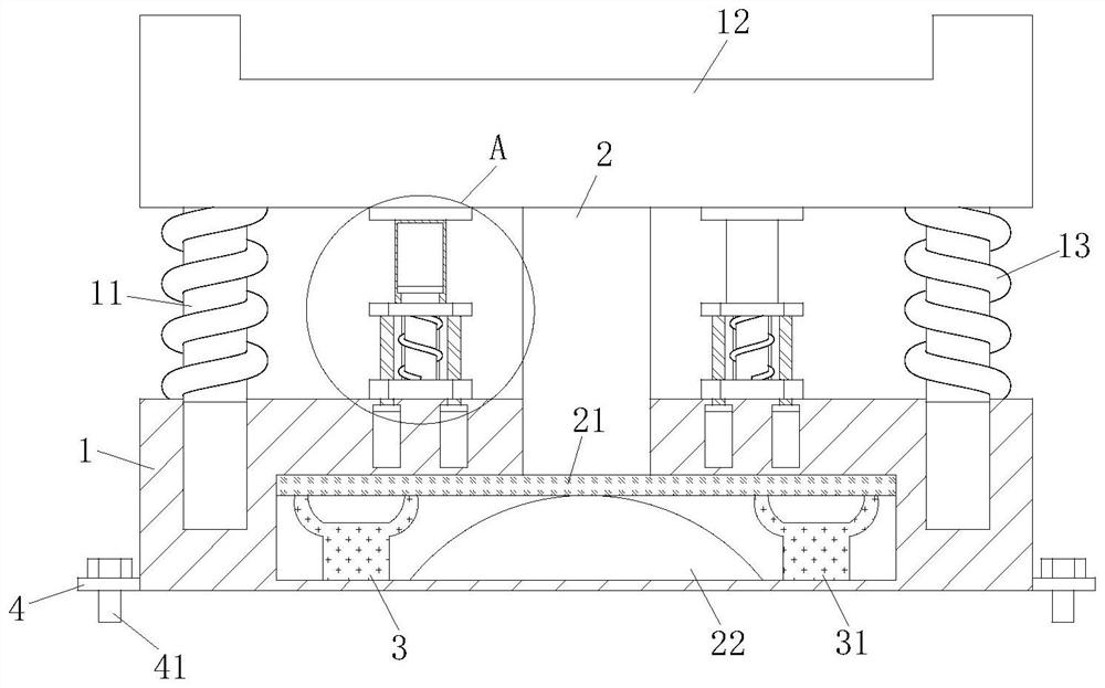
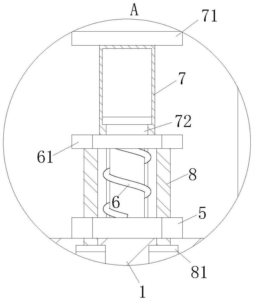
[0026] see Figure 1-4 As shown, a steam turbine safety auxiliary equipment includes a supporting square base 1 and a shock absorbing unit; the shock absorbing unit is arranged on the side wall of the supporting square base 1; the shock absorbing unit includes a supporting slide bar 11 and a concave placement plate 12 1. No. 1 elastic member 13 and buffer mechanism; the support slide bar 11 is slidably connected to the inner side wall of the support square base 1; the concave surface placement plate 12 is fixedly connected to the end of the support slide bar 11; the No. 1 elastic member 13 is socketed on the side wall of the supporting slide bar 11; the buffer mechanism is arranged at the bottom of the concave placing plate 12; during work, the staff installs the steam turbine on the end of the concave placing plate 12, when the steam turbine shakes during operation, The concave placing plate 12 will be pressed downwards, the concave placing plate 12 will press the four sets o...

Embodiment 2

[0035] see Figure 5 As shown in Comparative Example 1, as another embodiment of the present invention, the end of the connecting plate 5 is fixedly connected with an elastic protective pad 9; the shape of the elastic protective pad 9 is circular; when working, The steam turbine vibrates in operation, driving the concave surface placing plate 12 to press the pressing plate 61, the pressing plate 61 slides downward, and is pressed on the elastic protective pad 9 fixedly connected to the end of the connecting plate 5, and the elastic protective pad 9 fixedly connected to the end of the connecting plate 5 The pad 9 plays the role of cushioning and shock absorption, and avoids wear and tear caused by pressing and collision between the pressing plate 61 and the connecting plate 5 .

[0036] Working principle, when working, the staff installs the steam turbine on the end of the concave placing plate 12, when the steam turbine shakes during operation, the concave placing plate 12 wil...


PUM


Abstract

The invention belongs to the field of steam turbines, and particularly relates to steam turbine safety auxiliary equipment which comprises a supporting square base and a damping unit. The damping unit is arranged on the side wall of the supporting square base; the damping unit comprises a supporting sliding rod, a concave surface placing plate, a first elastic piece and a buffering mechanism; the supporting sliding rods are connected to the inner side wall of the supporting square base in a sliding mode. By means of the damping unit, when the steam turbine shakes after working for a long time, the steam turbine can press a concave face containing plate, the concave face containing plate presses a main connecting column at the bottom end and multiple sets of supporting sliding rods, the main connecting column and the supporting sliding rods slide on the inner side wall of a supporting square base at the same time, and a first elastic piece is pressed by the concave face containing plate to be shrunk and stressed; and an extrusion sliding plate extrudes a buffer air bag, a first rubber block and a second rubber block, the effect of enhancing the damping effect is achieved through the elasticity of multiple sets of elastic parts, and the situation that the parts are loosened and damaged due to long-time shaking of the steam turbine is avoided.

Description

technical field [0001] The invention relates to the field of steam turbines, in particular to a steam turbine safety auxiliary equipment. Background technique [0002] A steam turbine is a steam turbine engine and a rotating power device. [0003] The steam turbine is an external combustion rotary device that converts steam heat energy into mechanical work. Steam in the machine performs energy conversion in different ways, and converts steam heat energy into mechanical energy for the rotation of the steam turbine rotor. When installing the steam turbine, a special base is used for assembly . [0004] The shock absorption effect of the base equipped with the existing steam turbine is poor, and the steam turbine will vibrate during the operation process. In the case of long-term vibration, the internal parts of the steam turbine will appear loose. Therefore, in view of the above problems, a Auxiliary equipment for steam turbine safety. Contents of the invention [0005] I...

Claims


Application Information

Patent Timeline
Patent Type & Authority Applications(China)
IPC IPC(8): B65D61/00B65D85/68F16F15/08F16F15/023F16F15/02
CPCB65D61/00B65D85/68F16F15/08F16F15/023F16F15/022
Inventor 矫健刘小艳王玄晔
Owner GRAND NEW POWER
Learn More