Gasifier system and semi-coke distribution control method

A gasification furnace and semi-coke technology, applied in the field of coal gasification, can solve the problems of uncoordinated distribution ratio of semi-coke, unstable entrainment of synthetic gas, and unstable operation of the lock bucket system, and achieve the effect of improving processing efficiency

Active Publication Date: 2022-07-26
ENN SCI & TECH DEV
View PDF7 Cites 0 Cited by
  • Summary
  • Abstract
  • Description
  • Claims
  • Application Information

AI Technical Summary

Problems solved by technology

[0003] In order to make the overall system run at full load, it is necessary to keep the amount of semi-coke processed by the two sets of lock bucket systems stable during the cycle period. The coke amount cannot be determined, resulting in the inability of the attached lock bucket system to operate stably, resulting in an uncoordinated overall semi-coke distribution ratio, making the system unable to meet the long-term full-load stable operation

Method used


Image

  • Gasifier system and semi-coke distribution control method
  • Gasifier system and semi-coke distribution control method
  • Gasifier system and semi-coke distribution control method

Examples


Embodiment 1

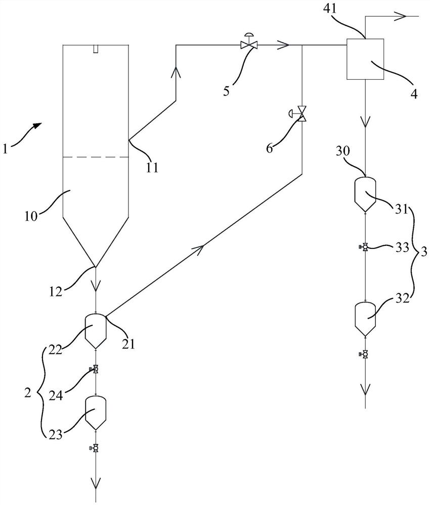
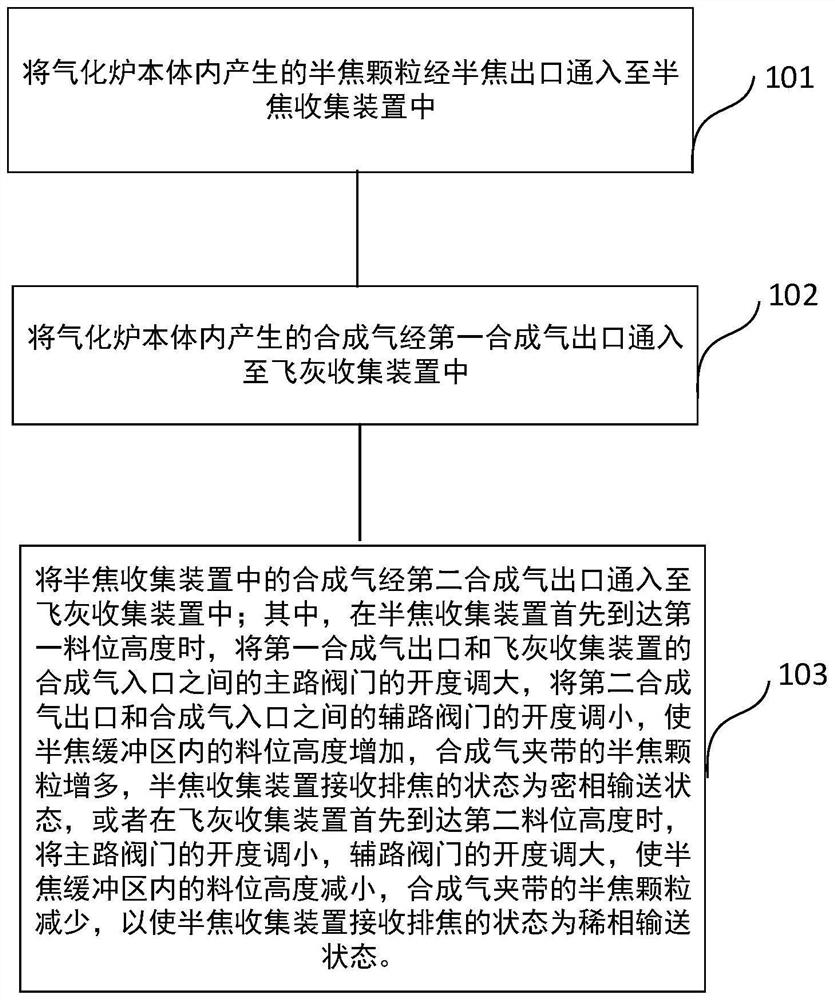
[0038] like figure 1 and 2 As shown, this embodiment provides a gasifier system, which includes a gasifier body 1, a semi-coke collecting device 2 and a fly ash collecting device 3, wherein,

[0039]The gasifier body 1 has a semi-coke outlet 12 and a first synthesis gas outlet 11, the semi-coke collecting device 2 is used to collect the semi-coke particles produced by the reaction in the gasifier body 1, and the semi-coke outlet 12 of the gasifier body 1 is communicated with To the semi-coke collecting device 2, the semi-coke collecting device 2 also has a second syngas outlet 21; the fly ash collecting device 3 is used to collect semi-coke particles entrained in the syngas produced by the reaction in the gasifier body 1, and the fly ash is collected The device 3 has a synthesis gas inlet, and both the first synthesis gas outlet 11 and the second synthesis gas outlet 21 are connected to the synthesis gas inlet 30 of the fly ash collection device 3, so that the synthesis gas i...

Embodiment 2

[0059] like Figure 3-5 As shown, the basic settings of the gasifier system in this embodiment are the same as those in Embodiment 1, and the only difference is:

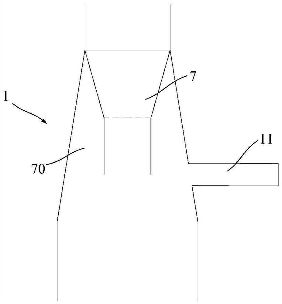
[0060] like image 3 As shown, the gasifier body 1 is also provided with an inner guide tube 7, the bottom area of ​​the gasifier body 1 forms a semi-coke buffer zone 10, the inner guide tube 7 is located above the semi-coke buffer zone 10, and the inner guide tube 7 An annular space 70 is formed between the outer wall of the flow cylinder 7 and the inner wall of the gasifier body 1 , and the first synthesis gas outlet 11 is communicated with the annular space 70 . The arrangement of the inner guide tube 7 can increase the flow rate of the synthesis gas at the central position of the gasification body, which is beneficial to the preliminary inertial separation of the semi-coke and the synthesis gas.

[0061] Since the efficiency of inertial separation is not stable enough to ensure that the amount of semi-coke ent...


PUM


Abstract

The present disclosure relates to a gasifier system and a semi-coke distribution control method. The gasifier system includes a gasifier body, a semi-coke collecting device and a fly ash collecting device, and the semi-coke outlet of the gasifier body is connected to the semi-coke collecting device. , the first synthesis gas outlet is connected to the fly ash collection device, and the semi-coke collection device is also connected to the inlet end of the fly ash collection device. There is an auxiliary valve between the fly ash collection devices. When the material level in the semi-coke collection device reaches the height of the first material level, the opening of the main valve increases, the opening of the auxiliary valve decreases, and the material level in the fly ash collection device rises. or when the material level in the fly ash collection device reaches the second material level, the opening of the main circuit valve decreases, the opening degree of the auxiliary circuit valve increases, and the material level in the semi-coke collection device increases, realizing the gasification Furnace systems are better adapted to optimal working conditions under full load operation.

Description

technical field [0001] The present disclosure relates to the technical field of coal gasification, and in particular, to a gasifier system and a semi-coke distribution control method thereof. Background technique [0002] Hydrogenation refers to the reaction of carbon-containing compounds and hydrogen at medium temperature (700~1000℃) and high pressure (5~10Mpa) to generate methane-rich crude gas, high value-added aromatic oil and high calorific value semi-coke. Gasifier is a common equipment used for gasification reaction. Usually, there is a semi-coke buffer zone at the bottom of the gasifier. After the reacted semi-coke and syngas undergo preliminary gas-solid inertial separation, most of the semi-coke falls into the semi-coke buffer zone, and then is discharged through the locking bucket system. A small part of the semi-coke is entrained by the syngas through the syngas outlet and enters the syngas filter for fine dust removal. The semi-coke separated during the process...

Claims


Application Information

Patent Timeline
Patent Type & Authority Patents(China)
IPC IPC(8): C10J3/52C10J3/72
CPCC10J3/52C10J3/723
Inventor 孙中卫周三刘明段所行王蕾
Owner ENN SCI & TECH DEV
Why Eureka
Try Eureka