


Quick Research
Generate reliable direction feasibility study reports for your R&D in just a few steps.

Technical Q&A
Discover and master advanced knowledge NOW. Basics, ideas, possibilities, all at once.

Find Solutions
As an expert in R&D theories, this can generate solutions to your technical problems instantly.

Evaluate Feasibility
Analyze your overall solution with one click, know your potential R&D risks in advance.

Monitor Landscape
Get weekly tech updates, stay abreast of the latest tech innovations and key insights.
Mounting structure of steel structure cantilever balcony
A technology for installing structures and steel structures, applied in balconies, measuring devices, building components, etc., can solve the problem of low stability of the connection between the cantilevered balcony and the floor body, excessive deformation of the connection of the I-beam, and poor integration effect. Good and other problems, to achieve the effect of increasing the stability of the connection, increasing the strength, and reducing the risk of falling off
- Summary
- Abstract
- Description
- Claims
- Application Information
AI Technical Summary
Problems solved by technology
Method used
Image

Examples
Embodiment 1
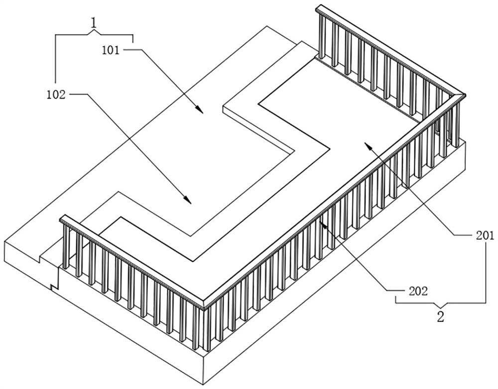
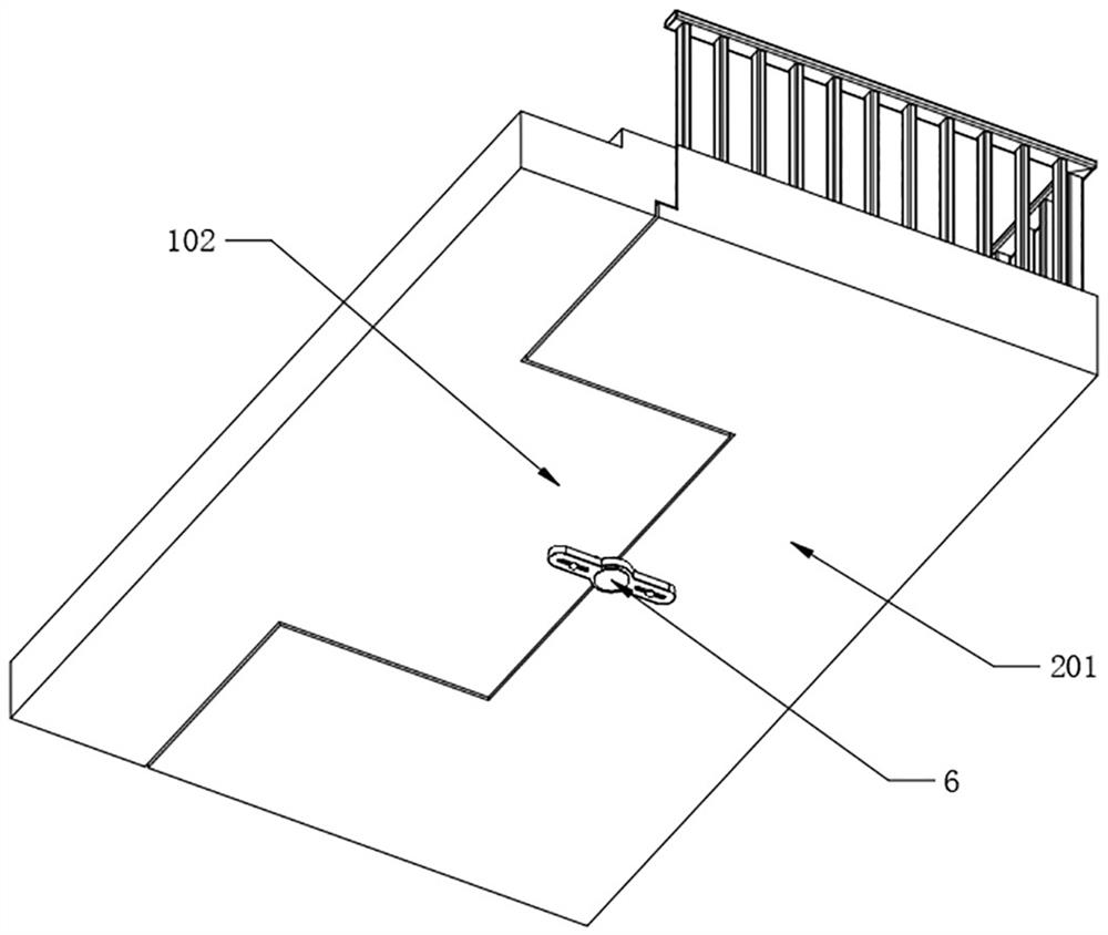
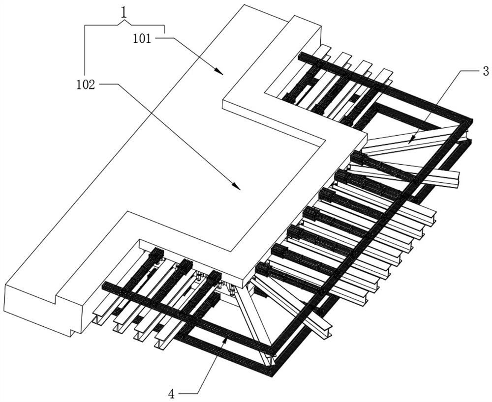
[0043] Refer to attached Figure 1-3 , the building body 1 also includes a floor body 101, one side of the outer wall of the floor body 101 is fixedly provided with a semi-suspended table body 102, the outer wall of the semi-suspended table body 102 is equidistantly fixedly connected with I-beams 3, and the outer wall of the semi-suspended table body 102 is fixed A steel bar connection structure 4 is provided, and a structure detector 6 is provided on the lower surface of the connection between the semi-suspended table body 102 and the suspended balcony 2;
[0044] Refer to attached Figure 4-5 The upper part of the outer wall of the semi-suspended table body 102 is fixedly provided with an upper boss 103, the lower part of the outer wall of the semi-suspended table body 102 is fixedly provided with a lower boss 104, and the I-beam 3 is connected in the gap between the upper boss 103 and the lower boss 104, And one end of the I-beam 3 is fixedly connected with the outer wall ...
Embodiment 2
[0050] Refer to attached Figure 6 A supporter 5 is installed on both sides of the joint between an I-beam 3 and the semi-suspended table body 102. The supporter 5 also includes a main body 501, and the side wall of the main body 501 is fixed with a T-shaped steel 502. Two T The T-shaped steel 502 is oppositely arranged on the outer wall of the I-shaped steel 3, and the two T-shaped steels 502 are fixedly connected by the assembly screws 503 arranged at the four corners. The supporters 5 are respectively installed, and the I-beam 3 and the two T-shaped steels 502 are fixedly connected by using the assembly screws 503 to pass through the I-beam 3. The structure of the supporter 5 is flexible, and the installation work is simple. The interior of Zigang 3 will not occupy additional space.
[0051] Refer to attached Figure 7 , the inside of the main body 501 is rotatably equipped with a double-threaded stud 505, and both ends of the main body 501 are slidably installed with sli...
Embodiment 3
[0055] Refer to attached Figure 8 , the structure detector 6 also includes an outer shell 601, and both ends of the outer shell 601 are provided with displacement grooves 602, one end inside the outer shell 601 is fixedly provided with a fixed pipe body 606, and the other end inside the outer shell 601 is slidably provided with a movable rod body 607, The end of the fixed pipe body 606 and the movable rod body 607 are fixedly provided with an insertion pin 604, the insertion pin 604 runs through the displacement groove 602, and the installation pin 604 containing the fixed pipe body 606 is rotatably connected to the lower surface of the semi-suspended table body 102 , the insertion pin 604 containing the live rod body 607 is rotatably connected to the lower surface of the suspension table 201, and the upper surface of the outer casing 601 is uniformly provided with a support spring 603 for separating from the wall, and the support spring 603 is used to make the gap between the...
PUM
 Abstract
Description
Claims
Application Information
 - R&D Engineer
- R&D Manager
- IP Professional
- Industry Leading Data Capabilities
- Powerful AI technology
- Patent DNA Extraction
Browse by: Latest US Patents, China's latest patents, Technical Efficacy Thesaurus, Application Domain, Technology Topic, Popular Technical Reports.
© 2024 PatSnap. All rights reserved.Legal|Privacy policy|Modern Slavery Act Transparency Statement|Sitemap|About US| Contact US: help@patsnap.com