

Dehumidifying and drying heat pump system fused with compressor driving type pseudo-loop heat pipe
A heat pump system and compressor technology, applied in heat pumps, dryers, dryers, etc., can solve the problems of lack of direct drive means, difficulty in guaranteeing application effects, poor economy, etc., so as to increase the proportion of latent heat and increase Large dehumidification energy efficiency, the effect of increasing the dehumidification capacity
- Summary
- Abstract
- Description
- Claims
- Application Information
AI Technical Summary
Problems solved by technology
Method used
Image

Examples
Embodiment 1
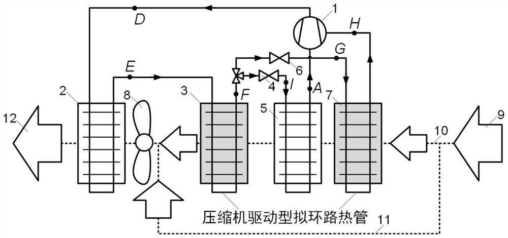
[0048] For a dehumidification and drying heat pump system incorporating a compressor-driven quasi-loop heat pipe in this embodiment, see figure 1 , mainly including compressor 1, condenser 2, condensation reheating section 3, throttle valve 4, evaporator 5, auxiliary throttle valve 6, evaporative precooling section 7 and fan 8.
[0049] In this embodiment, an air injection enthalpy-increasing compressor 1 with an intermediate air supply port is used, or a two-stage compression form in which two compressors are connected in series.
[0050] In this embodiment, the refrigerant flowing out from the condensation reheating section 3 is divided into two parts, one of which is throttled by the throttle valve 4 to a lower saturation temperature and then enters the evaporator 5, absorbs heat and evaporates from the air flowing through it, and then enters the compressor. machine 1; the other one is throttled to a higher saturation temperature by the auxiliary throttle valve 6 and then e...
Embodiment 2
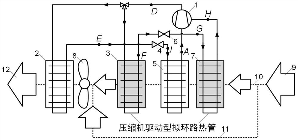
[0056] For a dehumidification and drying heat pump system incorporating a compressor-driven quasi-loop heat pipe in this embodiment, see image 3 , the main difference from Embodiment 1 lies in the arrangement of the refrigerant flow path.
[0057] In this embodiment, the high-temperature and high-pressure refrigerant at the outlet of the compressor 1 is directly divided into two, one of which is condensed by the condenser 2 to release heat to the air flowing through it, and then throttled by the throttle valve 4 to a low saturation temperature before entering the evaporator 5. After absorbing heat and evaporating from the passing air, it enters the compressor 1; the other way enters the condensing and reheating section 3 to condense and reheat the passing air, and then enters after throttling to a higher saturation temperature through the auxiliary throttle valve 6. The evaporative precooling section 7 enters the intermediate air supply port of the compressor 1 after absorbin...
Embodiment 3
[0061] The structure schematic diagram of this embodiment can be found in Figure 5 , the basic principle is consistent with that of Embodiment 1. Compared with Embodiment 1, the air flow path in this embodiment is not provided with the second air branch 11 for bypassing mixed air, so the condensation reheating section 3 in Embodiment 1 can be combined with the condenser 2, and the refrigerant Condensation and subcooling are all completed in the condenser 2 (the end of the refrigerant channel in the condenser 2 is the subcooling section). At this time, the evaporation precooling section 7 and the refrigerant subcooling section in the condenser 2 constitute a compressor-driven quasi-loop heat pipe in the present invention, which realizes the heat exchange effect of the air before and after the evaporator 5 . This form has a compact structure and high component integration, which is very suitable for application scenarios with limited installation space.
PUM
 Abstract
Description
Claims
Application Information