Cell analyzer and detection method thereof

An analyzer and white blood cell classification technology, which is applied in the analysis of materials, biological particle analysis, particle suspension analysis, etc., can solve the problems of high cost and large power source volume, reduce cost and volume, reduce the number of power sources, realize The effect of miniaturized design

Pending Publication Date: 2022-03-01
SHENZHEN MINDRAY BIO MEDICAL ELECTRONICS CO LTD
View PDF0 Cites 0 Cited by
  • Summary
  • Abstract
  • Description
  • Claims
  • Application Information

AI Technical Summary

Problems solved by technology

[0010] The first object of the present invention is to provide a cell analyzer, which aims to solve the technical problems of large volume and high cost of the power source of the existing cell analyzer

Method used


Image

  • Cell analyzer and detection method thereof
  • Cell analyzer and detection method thereof
  • Cell analyzer and detection method thereof

Examples


Embodiment 1

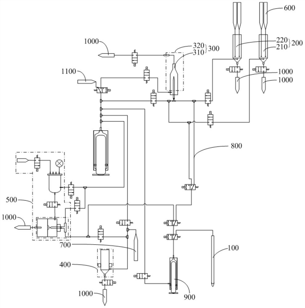
[0051] like Figure 1-3 As shown, the blood cell analyzer provided by Embodiment 1 of the present invention includes a sampling unit 100, an optical channel reaction cell 200, an optical detection unit 300, a hemoglobin detection unit 400, an impedance counting detection unit 500, a first reagent providing device 600, a second Second reagent supply device 700, delivery pipeline assembly 800, fluid power device 900, waste liquid tank 1000, diluent supply device 1100, sampling unit 100, optical channel reaction pool 200, optical detection unit 300, hemoglobin detection unit 400, impedance counting The detection unit 500 , the first reagent supply device 600 , the second reagent supply device 700 , the waste liquid pool 1000 , the diluent supply device 1100 and the fluid power device 900 are connected through the delivery pipeline assembly 800 to form a fluid circuit system.

[0052] In this embodiment, the fluid power device 900 includes a first injector 910 and a second injecto...

Embodiment 2

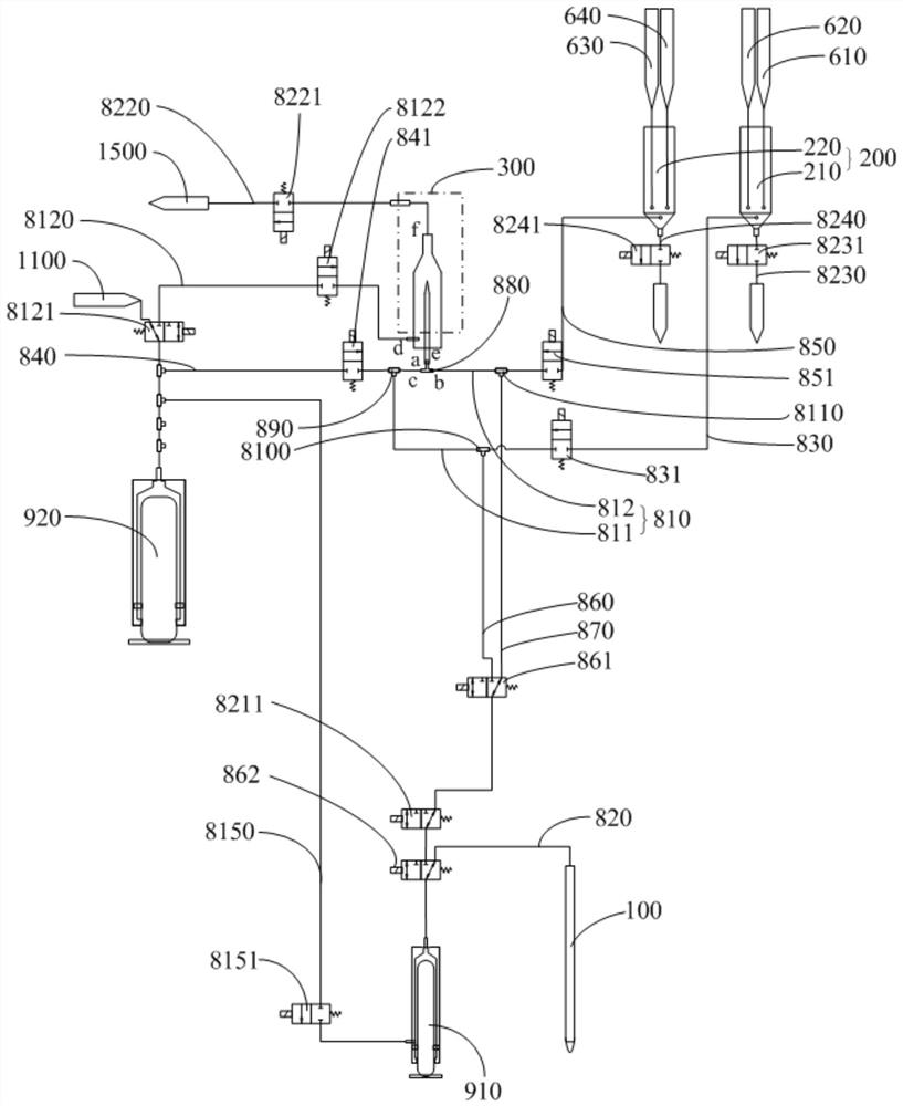
[0138] The difference between this embodiment and Embodiment 1 mainly lies in: the arrangement scheme of the optical sample preparation pipeline 810 is different. Such as figure 1 with figure 2 As shown, in Embodiment 1, the optical sample preparation pipeline 810 includes a first sample preparation pipeline 811 and a second sample preparation pipeline 812. In the leukocyte classification detection step and reticulocyte detection step, the leukocyte classification detection sample and the network The erythrocyte detection sample uses independent optical sample preparation pipeline 810 respectively; Figure 4 As shown, in this embodiment, the optical sample preparation pipeline 810 only includes the first sample preparation pipeline 811. In the leukocyte classification detection step and the reticulocyte detection step, the leukocyte classification detection sample and the reticulocyte detection sample share the same Sample prep tubing.

[0139] In this embodiment, the firs...

Embodiment 3

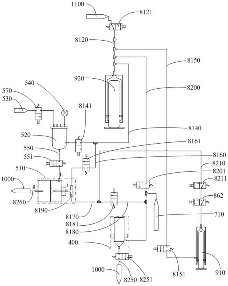
[0144] The difference between this embodiment and the second embodiment mainly lies in: the setting positions of the first sample preparation pipeline 811 and the first syringe 910 are different. Specifically, such as Figure 4 As shown, in the second embodiment, the first sample preparation pipeline 811 and the first syringe 910 are located upstream of the flow chamber 310, and the first syringe 910 pushes the upstream reticulocyte detection sample and white blood cell classification detection sample into the Detection is performed in the flow chamber 310; and as Figure 5 As shown, in this embodiment, the first sample preparation pipeline 811 and the first syringe 910 are located downstream of the flow chamber 310, and the first syringe 910 pushes the downstream reticulocyte detection sample and white blood cell classification detection sample into the Detection is performed in the flow chamber 310 .

[0145] The delivery pipeline assembly 800 also includes a first joint 8...


PUM


Abstract

The invention is suitable for the field of medical equipment, and discloses a cell analyzer and a detection method of the cell analyzer. The cell analyzer comprises a sampling part, an optical channel reaction tank, an optical detection unit, a hemoglobin detection unit, an impedance counting detection unit, a first reagent supply device, a second reagent supply device, a diluent supply device, a conveying pipeline assembly and a fluid power device, and the fluid power device comprises a first injector and a second injector. The measuring range of the first injector is smaller than that of the second injector, the second injector is used for driving an optical detection sample to be conveyed into the optical sample preparation pipeline from the optical channel reaction tank, and the first injector is used for providing power for sample suction, sample separation and sample pushing; the second injector is used for providing power for conveying the diluent to the flowing chamber, conveying the diluent to the hemoglobin detection unit, conveying the diluent to the impedance counting detection unit and preparing the sample. According to the invention, the cost and the size of the instrument are greatly reduced.

Description

technical field [0001] The invention relates to the field of medical equipment, in particular to a cell analyzer and a detection method of the cell analyzer. Background technique [0002] In order to drive the delivery of reagents and samples to achieve measurement, five-differential blood cell analyzers generally include a reagent delivery power source and a sampling push power source. [0003] Among them, the existing reagent delivery power sources mainly include the following design schemes: [0004] 1) The power source for reagent delivery adopts an external air source solution that can provide a large flow rate: this solution uses an external air source as the power source for reagent delivery, which can provide high pressure and large flow rate (generally provide no-load flow rate greater than 10L / min, pressure 200kPa or more), can drive cylinders, pneumatic pressure cut-off valves, pneumatic quantitative pumps and other components to work, and can drive to realize t...

Claims


Application Information

Patent Timeline
IPC IPC(8): G01N15/00G01N15/06G01N21/64G01N33/487G01N33/49G01N21/05
CPCG01N15/00G01N15/06G01N15/0656G01N33/48707G01N33/4915G01N21/6428G01N21/05G01N15/01G01N15/075
Inventor 石汇林滕锦朱春阳
Owner SHENZHEN MINDRAY BIO MEDICAL ELECTRONICS CO LTD
Why Eureka
Try Eureka