
Anti-collision prediction method and system of laser radar detection target

A laser radar, target detection technology, applied in radio wave measurement systems, measurement devices, electromagnetic wave re-radiation and other directions, can solve the problems of complexity, high performance requirements, high cost, reduce calculation and response pressure, and simplify the amount of sensor devices. , the effect of high accuracy

Pending Publication Date: 2022-03-01
雷神等离子科技(杭州)有限公司
View PDF10 Cites 0 Cited by
  • Summary
  • Abstract
  • Description
  • Claims
  • Application Information

AI Technical Summary

Problems solved by technology

[0004] In the prior art, multiple different types of sensors are often used to detect various types of parameter values ​​during the driving process of the car, and perform operations such as processing, calculation, and prediction, so as to guide the car to drive and prevent collisions. The method of obstacle avoidance and collision avoidance has the following technical problems: the number and types of detection and sensor devices used are large, the performance requirements for device response speed are high, and the performance requirements for devices responsible for processing, calculation and prediction operations are also high. , resulting in high cost, which limits market promotion and application
However, the road conditions in the driving process of the car are often complex, and the number of potential collision targets is also huge. The technical solution of the above patent may be limited when used in real scenes.

Method used


Image

  • Anti-collision prediction method and system of laser radar detection target
  • Anti-collision prediction method and system of laser radar detection target
  • Anti-collision prediction method and system of laser radar detection target

Examples


Embodiment 1

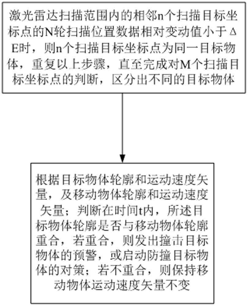
[0072] This embodiment proposes a collision avoidance prediction system that implements a laser radar detection target collision avoidance prediction method, including a laser radar module and a database, and sends and transmits signals between the laser radar module and a moving object, wherein,

[0073] 1. The parameters of the laser radar module are set as follows:

[0074] The transmission frequency f= 100khz, that is, the transmission period T = 10 -5 s = 10us;

[0075] Beam horizontal divergence angle θ (H) = 0.002rad;

[0076] Vertical divergence angle and collision prediction θ(V) = 0.01rad;

[0077] The scanning speed of the laser radar module is n= 40 revolutions / s; that is, the time required for the laser radar module to scan for one week is 0.025s;

[0078] Pulse width W = 10ns;

[0079] Transmit laser peak power P= 10W.

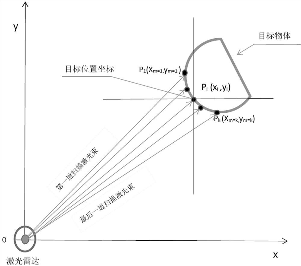
[0080] 2. The laser radar module scans and receives reflection data

[0081] The laser radar module is installed on a moving object and em...


PUM


Abstract

The invention discloses an anti-collision prediction method and system for a laser radar detection target, and belongs to the technical field of laser radar detection target anti-collision. Comprising the following steps: in target position data obtained by continuously scanning omnibearing laser radar pulses, if a group of adjacent target position data is approximately close to each other, and the target position data is approximately close to the same straight line through fuzzy logic operation, judging that the group of adjacent target position data belongs to the same target object; different target objects and contours and speeds of the target objects are recognized, and according to the speed and the contour of the moving object where the laser radar is located, whether the moving object collides with the target objects at the time t is calculated. Aiming at the technical problem of low accuracy in target tracking and collision avoidance, the method only depends on the scanning detection function of the laser radar, does not need excessive sensing devices, reduces the operation performance requirements of the devices, can accurately carry out collision avoidance prediction, is high in accuracy, reduces the use amount of the devices, and is low in cost.

Description

technical field [0001] The invention relates to the technical field of laser radar detection target collision avoidance, in particular to a laser radar detection target collision avoidance prediction method and system. Background technique [0002] The technology of automobile anti-collision has had many developments so far, and it is not difficult to find the target and determine its position and distance. However, it is difficult to track because there are many targets around, and it is very cumbersome to grasp all of their dynamics. It is necessary to process a large amount of data, including identifying whether the same target is the same, and the time allowed for processing is very limited. The automatic collision avoidance system (automaticcollision avoidance system) is a part of the smart car. The car anti-collision system is an intelligent device that prevents cars from colliding. It can automatically detect vehicles, pedestrians, or other obstacles that may collid...

Claims


Application Information

Patent Timeline
IPC IPC(8): G01S17/931G01S17/66
CPCG01S17/931G01S17/66
Inventor 孔德华黄保家金浩强
Owner 雷神等离子科技(杭州)有限公司
Features
  • Generate Ideas
  • Intellectual Property
  • Life Sciences
  • Materials
  • Tech Scout
  • Unparalleled Data Quality
  • Higher Quality Content
  • 60% Fewer Hallucinations
Learn More