Optical fiber vibration early warning system for pipe gallery

A fiber optic vibration and early warning system technology, which is applied to alarms, wave/particle radiation, artificial islands, etc., can solve problems such as difficult all-round, all-day monitoring, manual inspections involving a large number of people, and poor timeliness of manual inspections. , to achieve the effect of improving rapid response and safety prevention and control capabilities, good protection effect, and ensuring sensitive detection performance

Inactive Publication Date: 2022-03-01
江苏艾普泰克智能科技有限公司
View PDF0 Cites 1 Cited by
  • Summary
  • Abstract
  • Description
  • Claims
  • Application Information

AI Technical Summary

Problems solved by technology

[0003] At present, the monitoring methods of pipe gallery mainly include the following three types: the first one is manual inspection and monitoring; regular inspection of water leakage, cracks and other phenomena to find possible diseased areas; manual inspection has poor timeliness, and it is difficult Carry out monitoring, resulting in a blank inspection period, a large number of people involved in manual inspection, and cumbersome management process; the second type, robot monitoring; sensors are built into the robot, and various monitoring and detection in the pipe gallery are completed during the inspection process; robot monitoring exists monitoring Blind areas, and it is easy to cause safety hazards to gas pipelines; the third type, integrated monitoring and alarm system; integrated equipment and environmental monitoring, video monitoring, personnel intrusion monitoring, fire alarm, voice communication, power monitoring and other subsystems; integrated monitoring Failure to detect damage to pipe gallery walls

Method used


Image

  • Optical fiber vibration early warning system for pipe gallery
  • Optical fiber vibration early warning system for pipe gallery
  • Optical fiber vibration early warning system for pipe gallery

Examples


Embodiment Construction

[0031] In order to make the purposes, technical solutions and advantages of the embodiments of the present application clearer, the technical solutions in the embodiments of the present application will be clearly and completely described below in conjunction with the drawings in the embodiments of the present application. Obviously, the described embodiments It is a part of the embodiments of this application, not all of them. In the following description, specific details, such as specific configurations and components, are provided merely to help a comprehensive understanding of the embodiments of the present application. Accordingly, those of ordinary skill in the art should recognize that various changes and modifications of the embodiments described herein can be made without departing from the scope and spirit of the application. Also, descriptions of well-known functions and constructions are omitted in the embodiments for clarity and conciseness.

[0032] It should b...


PUM


Abstract

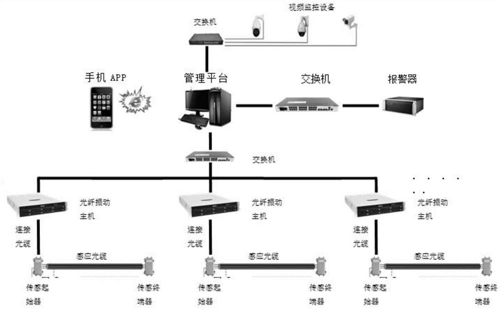
The invention relates to an optical fiber vibration early warning system for a pipe gallery. The optical fiber vibration early warning system comprises a management platform, two or more early warning subsystems, two or more video monitoring devices and an alarm. The management platform is connected with the early warning subsystem, the video monitoring device and the alarm. Each early warning subsystem comprises a sensing terminal device, a sensing initiator and an optical fiber vibration host; the sensing terminator is connected with the sensing initiator through a sensing optical cable, and the optical fiber vibration host is connected with the sensing initiator through a connecting optical cable. Abnormal conditions in the pipe gallery are monitored according to the optical fiber vibration principle, long-distance real-time seamless monitoring on the vibration condition of soil along the pipe gallery can be achieved, and accurate target positioning is conducted on a damage event through accurate vibration signal analysis; omnibearing and real-time online monitoring and real-time alarming of the underground comprehensive pipe gallery can be achieved, and the rapid response and safety prevention and control capacity of operation management of the urban underground comprehensive pipe gallery are greatly improved.

Description

technical field [0001] The invention relates to the technical field of monitoring and early warning of pipe gallery, in particular to an optical fiber vibration early warning system for pipe gallery. Background technique [0002] With the rapid development of economic construction and the increase of urban population, the scale of cities continues to expand, and many cities have problems such as shortage of construction land, road traffic congestion, insufficient urban infrastructure, and increased environmental pollution. These problems make us turn our attention to the underground space. If the urban underground space can be fully and rationally developed and utilized, its area can reach 50% of the urban ground area, which is equivalent to increasing the usable area of ​​the city by half. The construction of a comprehensive pipe corridor system can effectively alleviate the contradiction between urban development and land resource shortage, and is of great significance to ...

Claims


Application Information

Patent Timeline
Patent Type & Authority Applications(China)
IPC IPC(8): G08B21/18E02D29/045G01H9/00
CPCG08B21/18E02D29/045G01H9/004
Inventor 陈茂云刘霞
Owner 江苏艾普泰克智能科技有限公司
Why Eureka
Try Eureka