
Heat dissipation control system applied to power cabinet

A control system and power cabinet technology, applied in the cooling/ventilation of substation/switchgear, electrical components, substation/distribution device housing, etc., can solve the problem of insufficient heat dissipation, reduce safety hazards, and improve the efficiency of judgment and adjustment , the effect of sufficient heat dissipation

Active Publication Date: 2022-03-01
DAQING POWER SUPPLY COMPANY OF STATE GRID HEILONGJIANG ELECTRIC POWER COMPANY +1
View PDF13 Cites 0 Cited by
  • Summary
  • Abstract
  • Description
  • Claims
  • Application Information

AI Technical Summary

Problems solved by technology

[0004] For this reason, the present invention provides a heat dissipation control system applied to the power cabinet to overcome the problem of insufficient heat dissipation of the heat dissipation system of the power cabinet in the prior art

Method used


Image

  • Heat dissipation control system applied to power cabinet

Examples


Embodiment Construction

[0043] In order to make the objects and advantages of the present invention clearer, the present invention will be further described below in conjunction with the examples; it should be understood that the specific examples described here are only for explaining the present invention, and are not intended to limit the present invention.

[0044] Preferred embodiments of the present invention are described below with reference to the accompanying drawings. Those skilled in the art should understand that these embodiments are only used to explain the technical principle of the present invention, and are not intended to limit the protection scope of the present invention.

[0045] It should be noted that, in the description of the present invention, terms such as "upper", "lower", "left", "right", "inner", "outer" and other indicated directions or positional relationships are based on the terms shown in the accompanying drawings. The direction or positional relationship shown is ...


PUM


Abstract

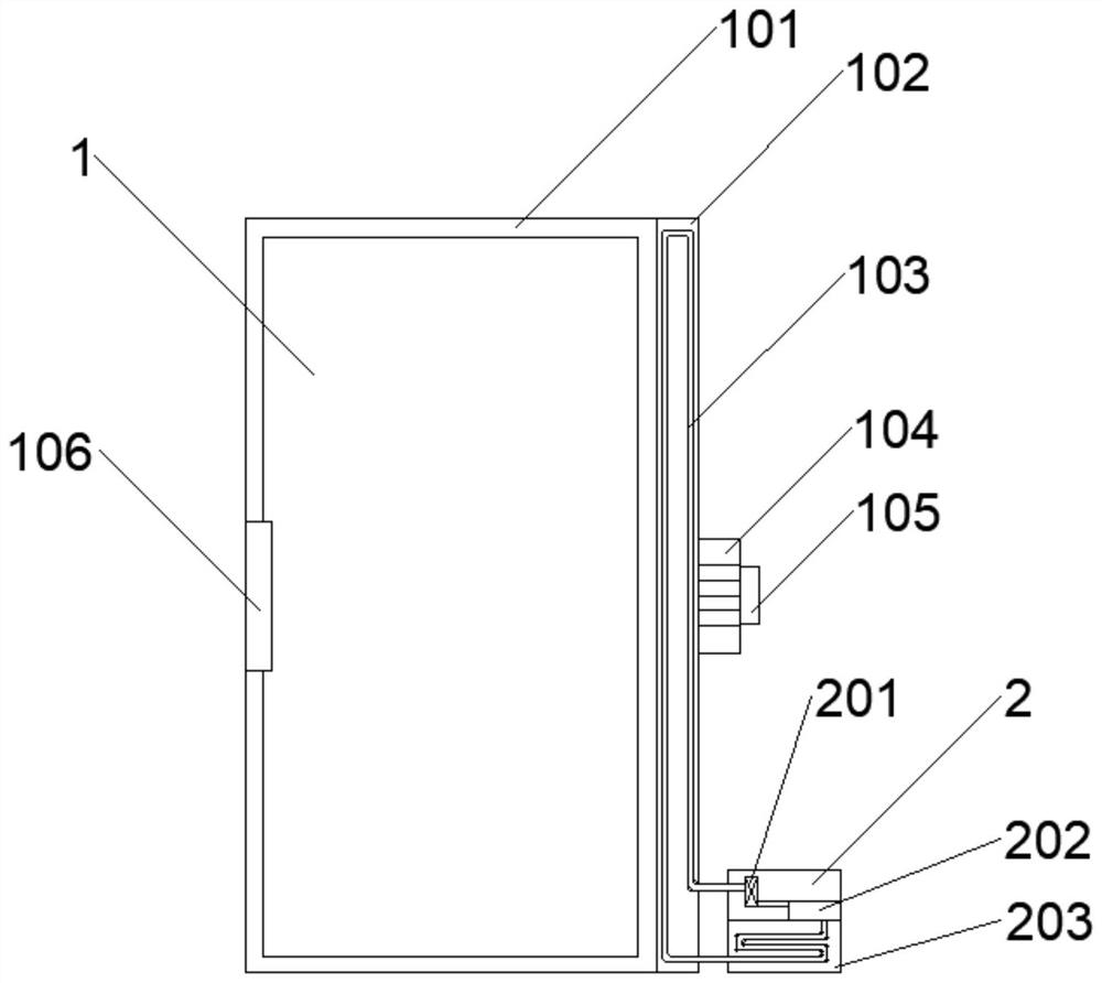
The invention relates to a heat dissipation control system applied to an electric power cabinet, and the system comprises an electric power cabinet unit, a cooling cabinet unit, and a central control unit. The heat dissipation layer is arranged in the power cabinet unit, the heat exchange coil pipe is arranged in the heat dissipation layer, so that the heat dissipation effect in the power cabinet unit is achieved, the central control unit adjusts the heat dissipation efficiency of the heat dissipation layer by controlling an opening valve in the cooling cabinet unit, and the cooling layer is arranged to cool a coolant in the heat exchange coil pipe, so that the heat dissipation efficiency of the power cabinet unit is improved. Meanwhile, a temperature detection device is arranged to detect the real-time temperature, a flow speed detection device is arranged to detect the air flow speed, and a central control unit intelligently adjusts the opening degree of an opening degree valve and the rotating speed of a heat dissipation fan according to the real-time temperature and the air flow speed, so that heat dissipation in the power cabinet unit can be more sufficient; and potential safety hazards in the power cabinet unit are reduced.

Description

technical field [0001] The invention relates to the technical field of power cabinet heat dissipation, in particular to a heat dissipation control system applied to a power cabinet. Background technique [0002] Power cabinets are often used in power distribution. They are mainly used to install electronic components. Because the electronic components in the power cabinets generate high heat during operation, some power cabinets are equipped with cooling systems to ensure that the electronic components inside Components are functioning normally. [0003] The heat dissipation system of the existing power cabinet is mainly driven by the heat dissipation motor to rotate the heat dissipation fan, so as to discharge the heat in the power cabinet and lower the temperature. Because the heat dissipation system mode is too simple and the emergency response capability is poor, it cannot cope with the temperature change inside the power cabinet. As a result, the internal heat dissipat...

Claims


Application Information

Patent Timeline
IPC IPC(8): H02B1/56H02B1/30H02B1/28
CPCH02B1/565H02B1/30H02B1/28
Inventor 王佐李少飞田野刘洋郎宇宁马兴明周义民苏文娟杨东海张环宇黄广佀相波祁晓春吴瑶卢志国于梦
Owner DAQING POWER SUPPLY COMPANY OF STATE GRID HEILONGJIANG ELECTRIC POWER COMPANY
Learn More