Bulk material chip mounting tray based on full-automatic chip mounter

A placement machine, fully automatic technology, applied in the direction of electrical connection formation of printed components, electrical components, printed circuit manufacturing, etc., can solve the problems of occupying the placement material level, solder can not be welded in time, increase the cost of circuit analysis, etc., to improve The effect of placement accuracy, improvement of placement work efficiency, and meeting the needs of small batch production

Pending Publication Date: 2022-03-01
EAST CHINA INST OF OPTOELECTRONICS INTEGRATEDDEVICE
View PDF0 Cites 0 Cited by
  • Summary
  • Abstract
  • Description
  • Claims
  • Application Information

AI Technical Summary

Problems solved by technology

[0002] As the number of newly developed products increases, the demand for small-batch trial production of circuits and secondary screening of components for high-reliability circuits also increases accordingly, which causes more and more circuits to be processed in bulk
[0003] At present, most automatic placement machines have certain requirements for the packaging of components, such as tape and reel packaging, cylindrical packaging, this method is only suitable for mass production to reduce production costs; vibration feeders are suitable for small quantities There are many bulk materials, which cannot be used for small batches of bulk materials, and occupy the patch material position, and the types of operable components are limited; in addition, there is also a short-belt feeder to match the patch, but this method is suitable for shorter Taping, and the procurement cost is high; at this stage, for small batches of loose chips, more manual placement is used, but manual placement has low placement efficiency, long cycle, and solder cannot be welded in time, which affects There are many problems such as circuit reliability. At the same time, components are easy to be misplaced, and the cost of circuit analysis is also increased.

Method used


Image

  • Bulk material chip mounting tray based on full-automatic chip mounter
  • Bulk material chip mounting tray based on full-automatic chip mounter
  • Bulk material chip mounting tray based on full-automatic chip mounter

Examples


Embodiment Construction

[0018] In order to make the present invention more clear, a kind of automatic placement machine based bulk material placement tray of the present invention will be further described below in conjunction with the accompanying drawings. The specific embodiments described here are only used to explain the present invention and are not intended to limit the present invention. invention.

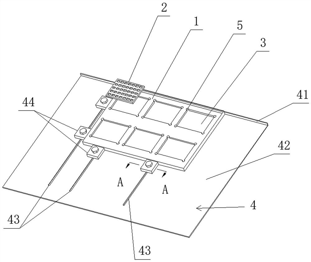
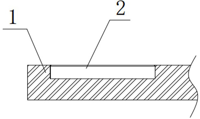
[0019] Such as figure 1 , figure 2 As shown, a bulk placement tray based on a fully automatic placement machine is used in conjunction with the KE-6060L placement machine. It includes a pallet 1 and a set of packaging boxes 2 (only one is shown in the figure). The supporting plate 1 is a rectangular plate made of Bakelite, and its upper and lower surfaces are parallel to each other. The packaging box 2 is the packaging box that comes with the bulk purchase, and does not need to be made separately. Here, the packaging box 2 is a rectangular box, which is a common shape on the market. The upper...


PUM


Abstract

The invention relates to a bulk chip mounting tray based on a full-automatic chip mounter, which comprises a supporting plate (1) and a group of packaging boxes (2), the upper surface of the supporting plate (1) is provided with a group of mounting grooves (3), each mounting groove (3) is matched with the corresponding packaging box (2) in appearance and clearance fit, the bottom of each packaging box (2) is arranged at the bottom of the corresponding mounting groove (3), the top surface of each packaging box (2) is flush with the upper surface of the supporting plate (1), and the upper surface of the supporting plate (1) is provided with a plurality of mounting grooves (3). The supporting plate (1) is detachably connected to a chip mounter bracket (4). According to the invention, through cooperation with full-automatic mounting equipment, the purpose of small-scale, batch, high-efficiency and high-quality mounting of multi-specification bulk materials is realized.

Description

technical field [0001] The invention relates to the technical field of surface assembly of hybrid integrated circuits, in particular to a bulk material placement tray based on a fully automatic placement machine. Background technique [0002] As the number of newly developed products increases, the demand for small-batch trial production of circuits and secondary screening of components for high-reliability circuits also increases accordingly, which causes more and more circuits to be processed in bulk. [0003] At present, most automatic placement machines have certain requirements for the packaging of components, such as tape and reel packaging, cylindrical packaging, this method is only suitable for mass production to reduce production costs; vibration feeders are suitable for small quantities There are many bulk materials, which cannot be used for small batches of bulk materials, and occupy the patch material position, and the types of operable components are limited; in...

Claims


Application Information

Patent Timeline
IPC IPC(8): H05K13/04H05K3/40
CPCH05K13/046H05K3/4007
Inventor 杜松臧子昂孙新宇
Owner EAST CHINA INST OF OPTOELECTRONICS INTEGRATEDDEVICE
Why Eureka
Try Eureka