Crop straw processing equipment for poultry feed

A technology of crop straw and processing equipment, which is applied in cutting equipment, application, agriculture, etc., and can solve the problems of inconvenient consumption by livestock and inconvenient packing of straw

Inactive Publication Date: 2022-03-04
黄升堂
View PDF1 Cites 1 Cited by
  • Summary
  • Abstract
  • Description
  • Claims
  • Application Information

AI Technical Summary

Problems solved by technology

[0005] In order to overcome the shortcomings of the above-mentioned patent that although the straw can be processed, the straw has not been crushed, and the uncrushed straw is inconvenient to be packaged, and it is not convenient for livestock to eat. Crop straw processing equipment for poultry feed for livestock

Method used


Image

  • Crop straw processing equipment for poultry feed
  • Crop straw processing equipment for poultry feed
  • Crop straw processing equipment for poultry feed

Examples


Embodiment 1

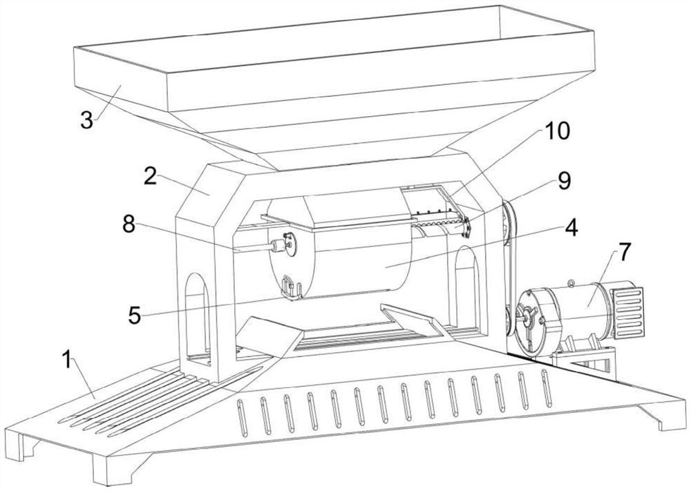
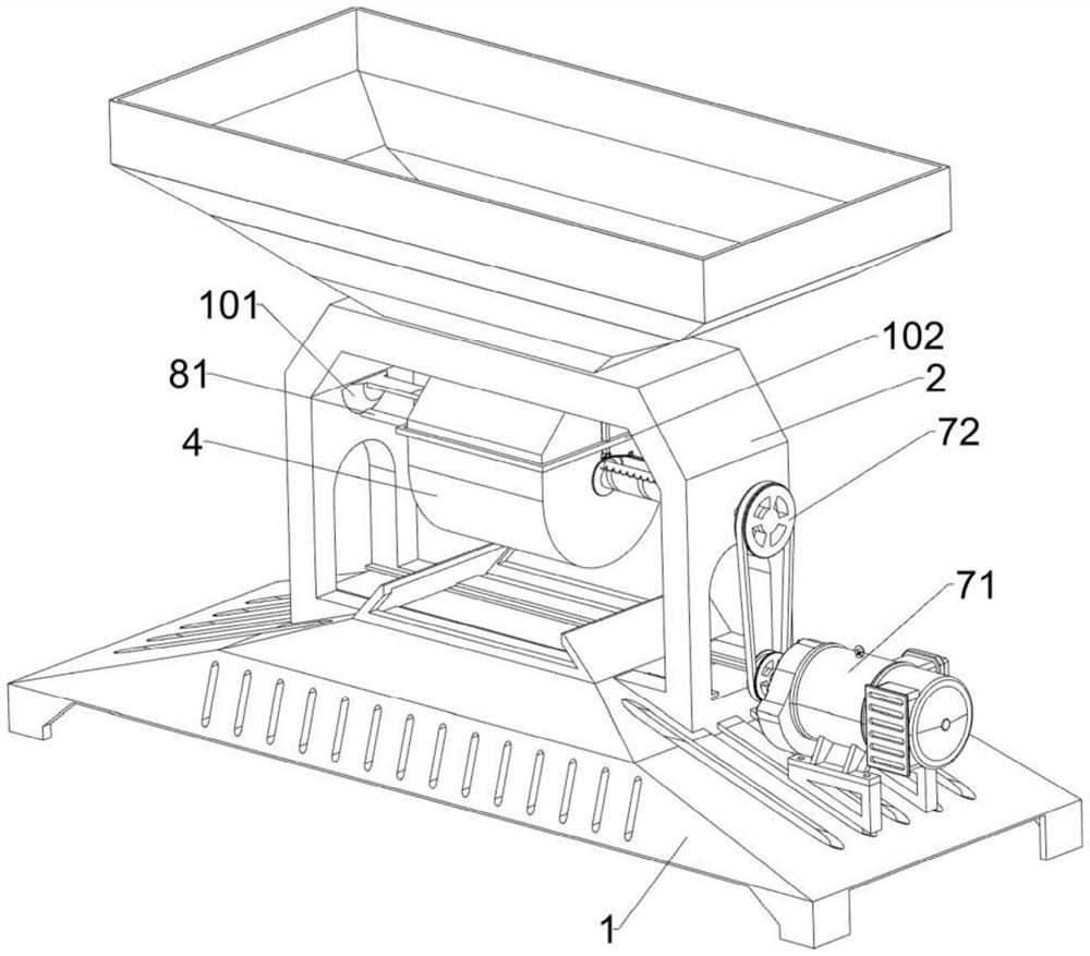
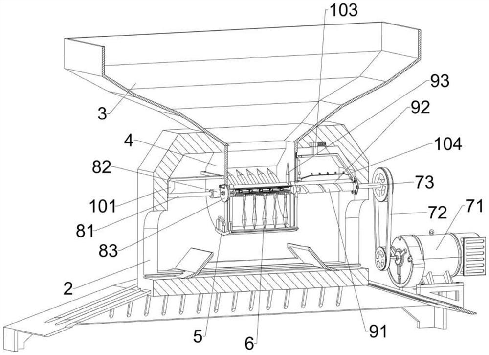
[0039] A crop straw processing equipment for poultry feed, including a base 1, an n-shaped seat 2, a lower hopper 3, a charging frame 4, an arc-shaped baffle 5, a cutter 6, a driving mechanism 7 and an auxiliary mechanism 8, please refer to figure 1 , figure 2 , image 3 , Figure 4 , Figure 6 , Figure 8 , Figure 9 , Figure 11 and Figure 12 As shown, an n-type seat 2 is installed in the middle of the top of the base 1 by welding, and a lower hopper 3 is installed in the middle of the outer top of the n-type seat 2 by welding. The operator can put the straw into the lower hopper 3, n A charging frame 4 is fixedly connected in the middle of the inner top of the mold seat 2. The top of the charging frame 4 is fixedly connected and communicated with the bottom of the lower hopper 3. The bottom of the charging frame 4 is open, and the front and rear sides of the opening of the charging frame 4 are There are arc-shaped baffles 5 slidingly connected between them, an auxi...

Embodiment 2

[0046] On the basis of Embodiment 1, it also includes a material cutting mechanism 9, and the material cutting mechanism 9 includes an outer spiral cylinder 91, a triangular sliding plate 92, a blade 93, an n-shaped frame 94, a movable rod 95, an arc block 96, the first A spring 97, a second spring 98 and a third spring 99, see figure 1 , image 3 , Figure 4 , Figure 8 , Figure 10 , Figure 13 , Figure 14 , Figure 15 , Figure 16 and Figure 17 As shown, a triangular sliding plate 92 is slidably connected between the upper parts of the turntables 83 on the left and right sides, the bottom of the triangular sliding plate 92 is in contact with the outer top of the cylinder 84, and the middle of the top of the triangular sliding plate 92 is slidably connected with a blade 93. When the blade 93 moves left and right, the blade 93 can cut off the stalks. The second spring 98 is symmetrically fixed between the inner bottom of the blade 93 and the inner top of the triangu...

Embodiment 3

[0051] On the basis of Embodiment 1 and Embodiment 3, it also includes a guide sleeve 11, a limit rod 12 and a pull ring 14, please refer to Figure 4 and Figure 5 As shown, there is a through hole 13 in the middle of the left part of the arc-shaped baffle plate 5, and a guide sleeve 11 is installed in the middle of the lower part of the outer left side of the charging frame 4 by welding. 12. The bottom end of the limit rod 12 runs through the through hole 13. The limit rod 12 can limit the position of the arc-shaped baffle 5. The top of the limit rod 12 is connected with a pull ring 14 by welding. When the operator pulls the When the ring 14 moves upward, the pull ring 14 can drive the limit rod 12 to move upward.

[0052] Also include fixed frame 15, scraper 16 and the fifth spring 17, please refer to Figure 4 , Figure 5 , Figure 14 , Figure 15 and Figure 16 As shown, the outer bottom of cylinder body 84 is left and right symmetrically installed with a fixed fram...


PUM


Abstract

The invention relates to processing equipment, in particular to crop straw processing equipment for poultry feed. The crop straw processing equipment for the poultry feed can smash straws, is convenient to package and is convenient for livestock to eat. Crop straw processing equipment for poultry feed comprises a base, an n-shaped seat, a discharging hopper and the like, the n-shaped seat is fixedly connected to the middle of the top of the base, and the discharging hopper is fixedly connected to the middle of the top outside the n-shaped seat. A proper amount of straw is put into the discharging hopper and falls into the loading frame, then the driving mechanism is started, the driving mechanism operates to drive the auxiliary mechanism to operate, the auxiliary mechanism operates to drive the cutter to rotate and rotate to smash the straw, and after all the straw is smashed, the driving mechanism is closed, so that the smashed straw is convenient to package and convenient for livestock to eat.

Description

technical field [0001] The invention relates to processing equipment, in particular to crop straw processing equipment for poultry feed. Background technique [0002] After the crops are harvested, some crops will be leftover, and the remaining part of the crops will be straw, which can be eaten by livestock such as cattle and sheep after processing, and the processing of straw needs to be crushed and packed, and then used after multi-process processing. [0003] The Chinese patent with the application number CN202120461197.4 discloses a straw processing device with the function of dust reduction, which includes a horizontal adjustment frame. A horizontal threaded rod is connected to the inside of the horizontally threaded slider, and a horizontal motor is connected to one side of the horizontally threaded rod, a spray port is connected to the bottom of the dust removal pipe, and a processing shell is arranged below the spray port. And the inside of the processing shell is ...

Claims


Application Information

Patent Timeline
IPC IPC(8): A01F29/04A01F29/09A01F29/14
CPCA01F29/04A01F29/09A01F29/14
Inventor 黄升堂
Owner 黄升堂
Why Eureka
Try Eureka