Sewage treatment system for constructional engineering

A sewage treatment system and construction engineering technology, which is applied in the field of sewage treatment systems for construction engineering, can solve the problems of poor sedimentation effect of construction engineering sewage and poor sedimentation efficiency, and achieve the effect of preventing accumulation and increasing sedimentation speed

Pending Publication Date: 2022-03-04
山东威如建设工程有限公司
View PDF9 Cites 0 Cited by
  • Summary
  • Abstract
  • Description
  • Claims
  • Application Information

AI Technical Summary

Problems solved by technology

Since the sediment in the sewage needs to move a certain distance from the suspension to the deposition position during the sedimentation treatment of construction sewage, when the sediment deposition distance is long, the sedimentation efficiency will become poor. At the same time, when a large amount of sediment is deposited, it is easy to accumulate in large quantities. If the staff does not clean it up in time, the sedimentation effect of construction sewage will deteriorate.

Method used


Image

  • Sewage treatment system for constructional engineering
  • Sewage treatment system for constructional engineering
  • Sewage treatment system for constructional engineering

Examples


Embodiment 1

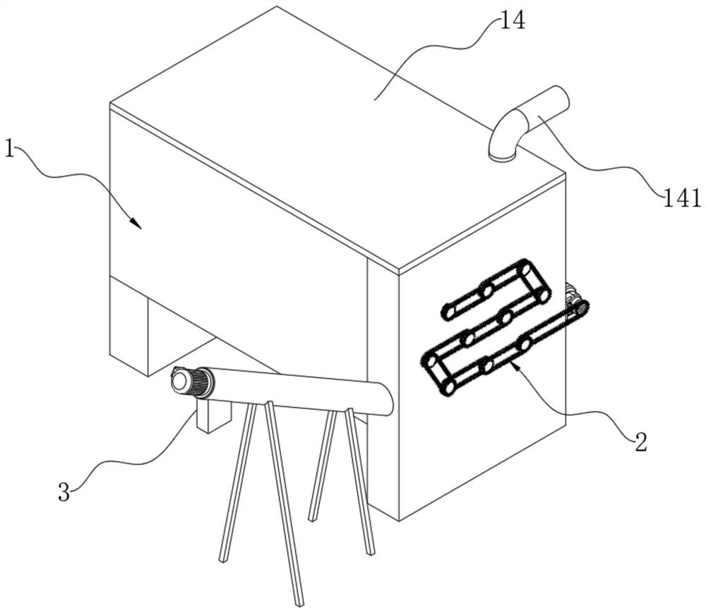
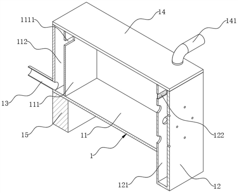
[0030] refer to Figure 1-Figure 8 , the sewage treatment system for construction engineering of the present invention comprises a treatment box 1, a settling chamber 11 is provided in the treatment box 1, a concentration bin 12 is arranged at the front end of the treatment box 1, and the rear end surface of the treatment box 1 is connected with The liquid outlet pipe 13, the top of the processing box body 1 is fixed with a top cover 14 by bolts, the top edge of the top cover 14 is connected with a liquid inlet pipe 141, and the end of the liquid inlet pipe 141 stretches into the bottom of the sedimentation chamber 11, by The sewage produced by the construction project is passed into the liquid inlet pipe 141 so that the sewage can be injected into the sedimentation chamber 11 so that the sewage can be settled in the sedimentation chamber 11 . The rear side of the sedimentation chamber 11 is tightly welded with a partition 111, and the top of the partition 111 is provided with...

Embodiment 2

[0036] In the above scheme, a sediment discharge structure 3 is installed on the centralized bin 12, and the sediment discharge structure 3 includes a fixed sleeve 31 tightly welded on the left end surface of the centralized bin 12, a pocket plate 32 tightly welded in the concentrated bin 12, and a sleeve. The major axis 33 is arranged in the fixed sleeve 31 .

[0037] In this embodiment, the fixed sleeve 31 communicates with the inside of the centralized warehouse 12, and the top end of the fixed sleeve 31 is tightly welded with an end sleeve 311, which is hollow and communicates with the inside of the fixed sleeve 31, and the periphery of the fixed sleeve 31 Several supporting legs 312 are tightly welded on the surface, and a helical blade 331 is tightly welded on the peripheral surface of the major axis 33. The top end of the long axis 33 in the plate 32 is coaxially connected with a conveying motor 332 , and the conveying motor 332 is fixed on the top surface of the fixed ...


PUM


Abstract

The invention discloses a sewage treatment system for constructional engineering, which comprises a treatment box body, a concentration bin is arranged at the front end of the treatment box body, a precipitation device is arranged in the treatment box body, a precipitate discharge structure is mounted on the concentration bin, and the precipitation device comprises a bottom plate, a plurality of precipitate conveying structures and a rotating motor. The sediment discharging structure comprises a fixing sleeve, a pocket plate and a long shaft. According to the sewage treatment device, the precipitation device is arranged, and a plurality of precipitation conveying structures are distributed in the precipitation cavity, so that silt in sewage can be more quickly precipitated into the precipitation conveying structures, the precipitation speed is increased, the precipitates can be directly discharged outwards through the precipitation discharging structure arranged on the concentration bin, and the precipitation efficiency is improved. Therefore, the purpose of cleaning sediments is achieved, and the sediments are prevented from being accumulated.

Description

technical field [0001] The invention belongs to the technical field of construction engineering sewage treatment, in particular to a sewage treatment system for construction engineering. Background technique [0002] Construction engineering sewage refers to the sewage generated during construction projects. During construction projects, the sewage generated is mainly mixed with a large amount of sediment. If the construction engineering sewage is directly discharged into the municipal drainage system, the sediment will be The municipal drainage system is clogged. Therefore, during construction projects, the sewage generated is usually discharged after sedimentation treatment to prevent a large amount of sediment from clogging the municipal drainage system. Since the sediment in the sewage needs to move a certain distance from the suspension to the deposition position during the sedimentation treatment of the construction engineering sewage, when the sediment deposition dist...

Claims


Application Information

Patent Timeline
Patent Type & Authority Applications(China)
IPC IPC(8): B01D21/02B01D21/00B01D21/24
CPCB01D21/02B01D21/0051B01D21/0006B01D21/2461
Inventor 吴敏华朱帅龙徐玉殿
Owner 山东威如建设工程有限公司
Why Eureka
Try Eureka