Recycling device for demolition steel of steel structure building

A steel structure and building technology, applied in positioning devices, manufacturing tools, metal processing machinery parts, etc., can solve the problems of low processing efficiency, inability to cut disk positioning and cutting, etc., to ensure stability and facilitate the effect of supporting the limit.

Active Publication Date: 2022-03-04
河北钢山杭萧钢结构工程股份有限公司
View PDF7 Cites 0 Cited by
  • Summary
  • Abstract
  • Description
  • Claims
  • Application Information

AI Technical Summary

Problems solved by technology

[0003] At present, common recycling devices can only cut tubular steel, and cannot cut bent steel at its bends. The main reason is that there is no structure to fix this type of steel, and the cutting disc cannot be positioned accurately. To the bending of the steel, the cutting method of this kind of steel still needs manual cutting, which makes the overall processing efficiency low

Method used


Image

  • Recycling device for demolition steel of steel structure building
  • Recycling device for demolition steel of steel structure building
  • Recycling device for demolition steel of steel structure building

Examples


Embodiment 1

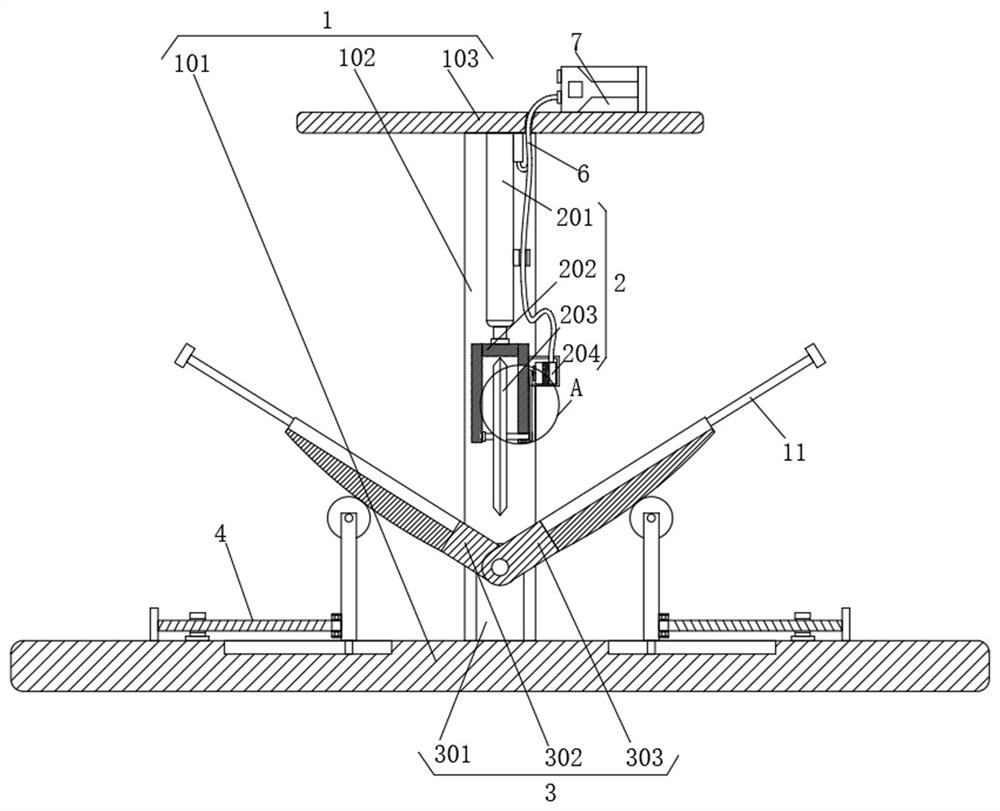
[0033] see figure 1 , figure 2 with image 3 , the steel structure demolition steel recycling device of the present invention includes a fixing assembly 1, a cutting assembly 2 and a supporting assembly 3, the fixing assembly 1 includes a base 101, a main rod 102 and a fixing plate 103, and the main rod 102 is fixedly installed on the base 101 The top of the top, the fixed plate 103 is fixedly installed on the top of the main rod 102, the cutting assembly 2 is fixedly installed on the bottom of the fixed plate 103, the support assembly 3 is arranged on the top of the base 101, and the bottom of the support assembly 3 is provided with an adjustment assembly 4.

[0034] Cutting assembly 2 comprises electric telescopic rod 201, mounting bracket 202, cutting disc 203 and motor 204, and electric telescopic rod 201 is fixedly installed on the bottom of fixed plate 103, and mounting frame 202 is fixedly installed on the bottom of electric telescopic rod 201, and cutting disc 203 is...

Embodiment 2

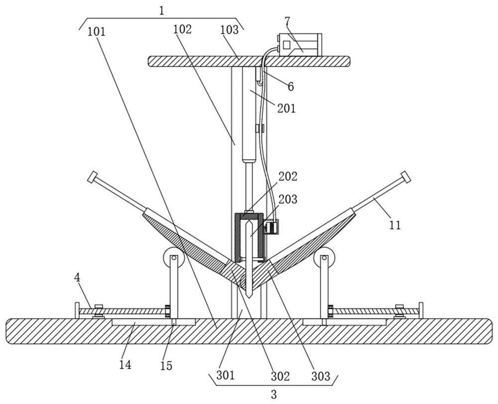
[0038] see figure 1 , Figure 4 and Figure 5 , the support assembly 3 includes a support column 301, a first support plate 302 and a second support plate 303, the support column 301 is fixedly installed on the top of the base 101, and the first support plate 302 and the second support plate 303 are both movably installed on the support through hinges. At the top of the column 301, the top surfaces of the first support plate 302 and the second support plate 303 are provided with a placement groove 8, and the sides of the first support plate 302 and the second support plate 303 are provided with concave holes 9, and the first support plate 302 and the side of the second support plate 303 are all movably connected with a movable frame 10, and the inwall of the movable frame 10 is fixedly connected with a push rod 11, and one end of the push rod 11 is inserted into the inside of the first support plate 302 and the second support plate 303, placed The inner wall of the groove 8 ...

Embodiment 3

[0042] see figure 1 , figure 2 and Figure 6 , the adjustment assembly 4 comprises a threaded rod 401, a movable plate 402 and a roller 403, a bearing is arranged between one end of the threaded rod 401 and the side of the movable plate 402, and the roller 403 is installed on the top of the movable plate 402 by rotating the rotating shaft, and the surface of the roller 403 Fitted with the bottom surface of the first support plate 302 and the second support plate 303, the top surface of the base 101 is provided with a chute 14, the inner wall of the chute 14 is movably connected with a slider 15, and the top of the slider 15 is connected with the movable plate 402. Fixed connection at the bottom.

[0043] The difference from Embodiment 2 is that an adjustment assembly 4 is provided at the bottom of the first support plate 302 and the second support plate 303, so that the threaded rod 401 on the adjustment assembly 4 drives the movable plate 402 to move left and right, so tha...


PUM


Abstract

The invention relates to the technical field of steel structure buildings, and particularly discloses a steel structure building demolition steel recycling device which comprises a fixing assembly, a cutting assembly and a supporting assembly, the fixing assembly comprises a base, a main rod and a fixing plate, the main rod is fixedly installed at the top of the base, and the fixing plate is fixedly installed at the top of the main rod; according to the steel cutting device, a base and a main rod on the fixing assembly are matched with each other to provide supporting force for the cutting assembly on the fixing plate, a motor in the cutting assembly drives a cutting disc to conduct cutting work, meanwhile, an electric telescopic rod can push the cutting disc downwards, and then steel on the supporting assembly is smoothly cut off; due to the fact that the supporting assembly is composed of the first supporting plate and the second supporting plate, bending of the steel can correspond to the connecting position of the first supporting plate and the second supporting plate, and therefore the cutting disc can be accurately positioned to the bending position of the steel, and accurate positioning cutting work is carried out.

Description

technical field [0001] The invention relates to the technical field of steel structure buildings, in particular to a device for recycling and reusing steel from demolished steel structure buildings. Background technique [0002] With the rapid development of the construction industry, various architectural styles have been developed. For example, steel structure buildings are a new type of building system. Compared with traditional concrete buildings, steel structure buildings are replaced by steel plates or section steel. Reinforced concrete is used, which has the characteristics of higher strength and better earthquake resistance, but there will be demolition when there is construction. When demolishing steel structure buildings, the demolished steel will be recycled. Cutting steel. [0003] At present, common recycling devices can only cut tubular steel, and cannot cut bent steel at its bends. The main reason is that there is no structure to fix this type of steel, and t...

Claims


Application Information

Patent Timeline
Patent Type & Authority Applications(China)
IPC IPC(8): B23D79/00B23Q3/00
CPCB23D79/00B23Q3/00
Inventor 武强宁凤群郭振兴
Owner 河北钢山杭萧钢结构工程股份有限公司
Why Eureka
Try Eureka