
Automatic welding equipment and welding process

An automatic welding and equipment technology, applied in welding equipment, auxiliary welding equipment, welding/cutting auxiliary equipment, etc., can solve problems affecting the smoothness of the tank body, sticking to the tank body, and affecting the welding stability of the tank body , to avoid scattering on the surface of the tank, to facilitate dumping, and to achieve better collection effects

Inactive Publication Date: 2022-03-04
徐州大业三维科技有限公司
View PDF0 Cites 0 Cited by
  • Summary
  • Abstract
  • Description
  • Claims
  • Application Information

AI Technical Summary

Problems solved by technology

[0003] At present, there are the following problems in the process of welding the tank body: a. The tank body will produce solder spatter particles during the welding process, and the solder spatter particles generated during the traditional welding process will directly drop on the tank body without being collected. , due to the high temperature of the solder spatter particles, it will adhere to the tank body after dripping on the tank body, affecting the smoothness of the tank body surface; b. When welding two tank bodies, it is often necessary to rely on manual methods or use The two drive sources respectively drive the tank body to rotate in a circumferential direction, which is prone to asynchronous rotation, resulting in a change in the relative position of the two tank bodies, affecting the accuracy of welding. The tank body may shake during the welding process, resulting in During the welding process, there will be a problem of virtual welding, which will affect the welding stability between the tanks

Method used


Image

  • Automatic welding equipment and welding process
  • Automatic welding equipment and welding process
  • Automatic welding equipment and welding process

Examples


Embodiment Construction

[0034] The embodiments of the present invention will be described in detail below with reference to the accompanying drawings, but the present invention can be implemented in many different ways defined and covered by the claims.

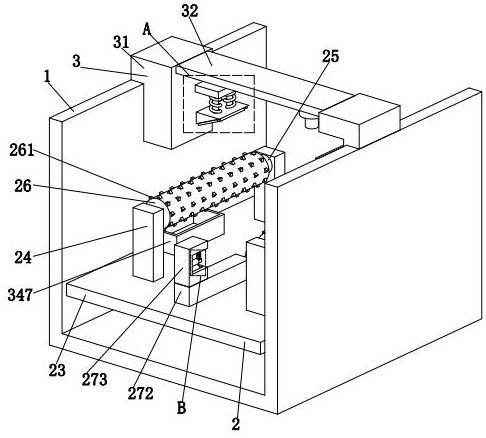
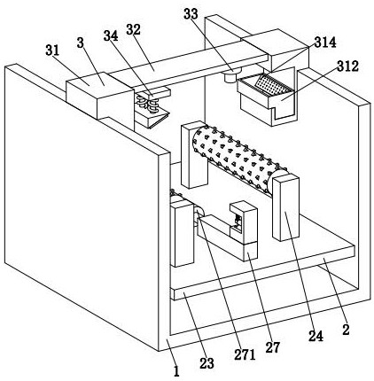
[0035] refer to figure 1 , an automatic welding equipment, including a supporting frame 1, a rotating mechanism 2 and a welding mechanism 3, the supporting frame 1 is a 匚-shaped structure with an upward opening, and the 匚-shaped structure consists of a horizontal section and two vertical sections. It consists of straight sections, a rotating mechanism 2 is installed on the upper end of the horizontal section of the supporting frame 1, and a welding mechanism 3 is installed between the two vertical sections of the supporting frame 1.

[0036] refer to figure 2 as well as Figure 5The rotating mechanism 2 includes a lifting cylinder 21, an adjusting frame 22, a support plate 23, a supporting frame 24, a rotating motor 25, a rotating roller 26 and a...


PUM


Abstract

The invention relates to the technical field of automatic welding, in particular to automatic welding equipment and a welding technology.The automatic welding equipment comprises a bearing rack, a rotating mechanism and a welding mechanism, and the rotating mechanism comprises a lifting air cylinder, an adjusting frame, a supporting plate, a supporting frame, a rotating motor, a rotating roller and a limiting branch chain; the welding mechanism comprises a welding rack, a welding truss, a welding machine and a polishing branch chain; the collecting frame provided by the invention can be used for collecting soldering tin splashing particles generated in the welding process, so that the problem that the soldering tin splashing particles are adhered to the surface of a tank body to influence the smoothness of the surface of the tank body is avoided; in the limiting branch chain, a bidirectional air cylinder drives a limiting block through a limiting plate to push the tank bodies to be attached more tightly, it is guaranteed that the tank bodies cannot shake in the welding process, and the problem of insufficient welding in the welding process is avoided.

Description

technical field [0001] The invention relates to the technical field of automatic welding, in particular to an automatic welding equipment and a welding process. Background technique [0002] Welding, also known as welding, is a manufacturing process and technology that combines metal or other thermoplastic materials by heating, high temperature or high pressure. There are many energy sources for modern welding, including gas flame, electric arc, laser, electron beam, friction and Ultrasonic, etc., usually metal materials such as tanks and rails are connected by welding. [0003] At present, there are the following problems in the process of welding the tank body: a. The tank body will produce solder spatter particles during the welding process, and the solder spatter particles generated during the traditional welding process will directly drop on the tank body without being collected. , due to the high temperature of the solder spatter particles, it will adhere to the tank ...

Claims


Application Information

Patent Timeline
Patent Type & Authority Applications(China)
IPC IPC(8): B23P23/04B23K37/04B23K3/08B23K101/12
CPCB23P23/04B23K37/0443B23K3/08B23K2101/125
Inventor 陈烜
Owner 徐州大业三维科技有限公司
Learn More