Supercharge Your Innovation With Domain-Expert AI Agents!

Silencer and compressor

A muffler and compressor technology, applied in the field of compressors, can solve problems such as the threat of pump body lubrication and low compressor superheat, and achieve the effects of solving insufficient superheat, increasing heat exchange, and reducing waste.

Pending Publication Date: 2022-03-04
SHANGHAI HITACHI ELECTRICAL APPLIANCES CO LTD
View PDF0 Cites 0 Cited by
  • Summary
  • Abstract
  • Description
  • Claims
  • Application Information

AI Technical Summary

Problems solved by technology

[0004] The purpose of the present invention is to provide a muffler and a compressor to solve the problem that the bottom superheat of the compressor is low during the start-up stage, which threatens the lubrication of the pump body

Method used


Image

  • Silencer and compressor
  • Silencer and compressor
  • Silencer and compressor

Examples


Embodiment 1

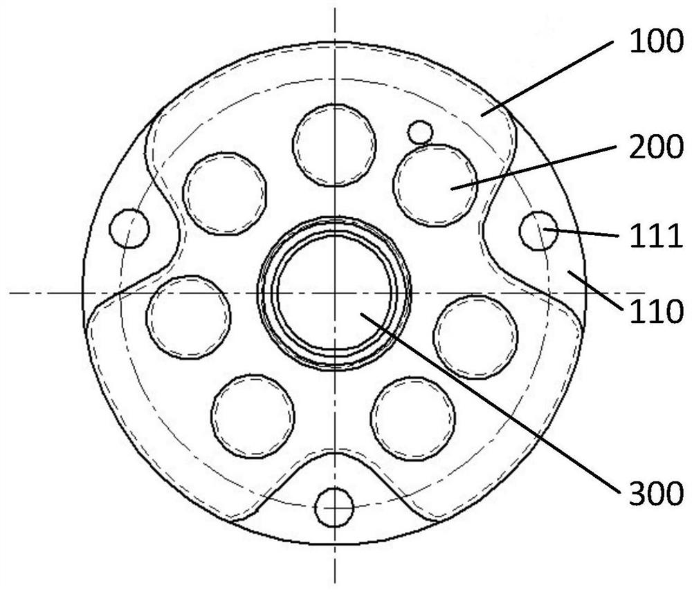
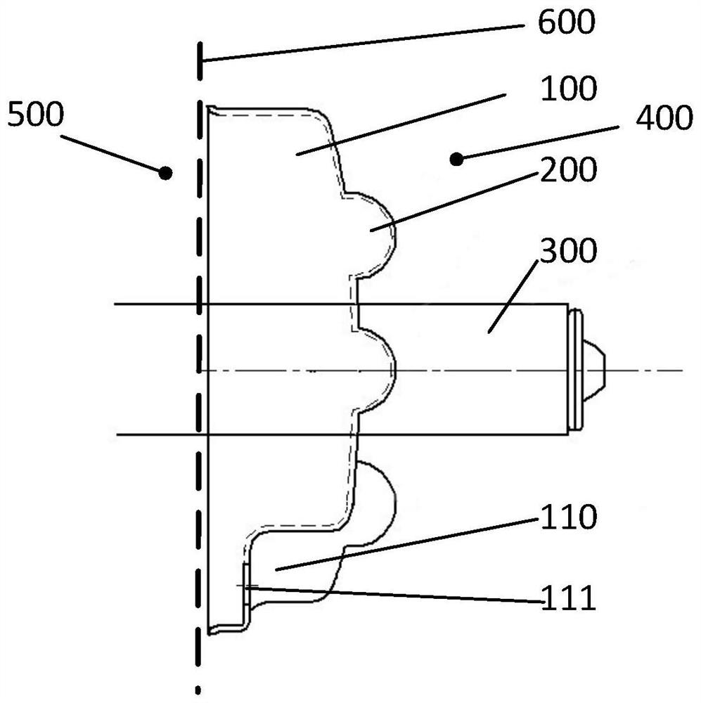
[0029] Please refer to figure 1 and figure 2 ,in, figure 1 It is the front view of the muffler of Embodiment 1 of the present invention; figure 2 It is the left side view of the muffler of Embodiment 1 of the present invention.

[0030] figure 1 and figure 2 A muffler is shown, which is applied to a compressor; the muffler is arranged between the oil storage part 400 and the refrigerant discharge chamber 500, and the muffler includes a main body 100 arranged in the axial direction and at least one protrusion 200, the raised portion 200 is arranged axially on the main body 100, and protrudes toward the oil storage portion 400; the contour of the projection of the raised portion 200 on a base surface 600 falls on the The main body 100 is within the outline of the projection on the base surface 600 . The base surface 600 is a reference surface perpendicular to the central axis of the muffler.

[0031] Among the existing compressors, there is a type of compressor that di...

Embodiment 2

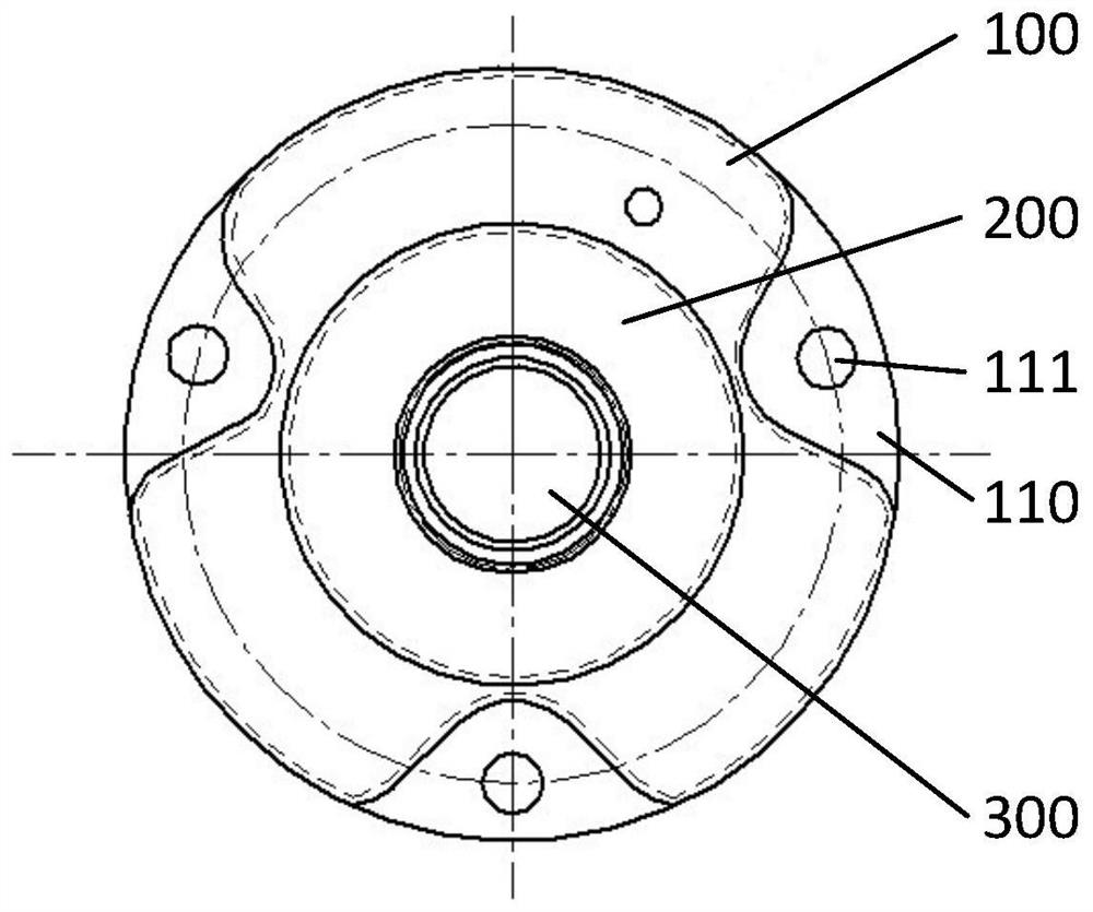
[0044] Please refer to image 3 and Figure 4 ,in, image 3 It is the front view of the muffler of Embodiment 2 of the present invention; Figure 4 It is the left side view of the muffler of the second embodiment of the present invention.

[0045] The difference between this embodiment and the first embodiment is that the protruding portion 200 includes a circular cylinder, and the axis of the circular cylinder coincides with the axis of the main body 100 . It should be understood that the circular gap in the middle of the raised portion 200 is designed to facilitate the crankshaft 300 passing through the muffler without interference. In one embodiment, when the crankshaft 300 of the compressor does not need to be arranged at the same position as the muffler, the muffler The raised portion 200 can also be a cylinder. It should be understood that the above-mentioned concepts of circular cylinder and cylinder are not concepts in the context of geometry, such as circular frus...

Embodiment 3

[0048] This embodiment provides a compressor, including a muffler, an oil storage part, and a refrigerant discharge chamber. For specific structural details of the muffler, reference may be made to Embodiment 1 or Embodiment 2.

[0049] In a preferred embodiment, the muffler is arranged between the oil storage part 400 and the refrigerant exhaust chamber 500, and the contact area between the muffler and the oil storage part 400 is the same as that of the oil storage part 400. Volume ratio greater than or equal to 15mm 2 / ml. The inventor first carried out data statistics on the operating conditions of the existing compressors, obtained the common temperature of the refrigerant exhaust chamber 500 at work, and then calculated the different volumes of the oil storage part 400 and the silencer through the thermodynamic simulation software. The final temperature of the oil after heat exchange under surface area conditions. Through the analysis and summary of the calculation resu...


PUM

PropertyMeasurementUnit
Wall thicknessaaaaaaaaaa

Abstract

The invention provides a silencer and a compressor, the silencer is arranged between an oil storage part and a refrigerant exhaust cavity, the silencer comprises a main body arranged in the axial direction and at least one protruding part, and the protruding part is arranged on the main body in the axial direction and protrudes towards the oil storage part; and the outline of the projection of the lug boss on a base plane is within the outline of the projection of the main body on the base plane. The base plane is a reference plane perpendicular to the central axis of the silencer. Through the configuration, the contact area of a refrigerant in the silencer and the oil storage part is increased, the heat exchange amount of the oil storage part and the pump body is improved, refrigerating machine oil can be rapidly heated, and therefore the problem that the superheat degree of the bottom of a compressor is insufficient in the starting stage is solved; and meanwhile, the heat of the refrigerant is fully utilized, and waste is reduced.

Description

technical field [0001] The invention relates to the field of compressors, in particular to a muffler and a compressor. Background technique [0002] Among the existing compressors, there is a type of compressor that discharges high-temperature refrigerant through the lower muffler. This type of compressor will encounter the following problems during operation: the pressure on the high-pressure side of the compressor is small during the start-up stage, and the pressure ratio of the compressor is also small, which is prone to low superheat at the bottom, resulting in the solubility of the refrigerant in the oil. Larger, low oil viscosity, the pump body lubrication is threatened. This problem is especially serious when the compressor uses refrigerants with low condensation temperatures such as R531A and R290. [0003] On the other hand, the heat of the refrigerant discharged from the exhaust port is not fully utilized, which also causes a certain degree of waste. Contents o...

Claims


Application Information

Patent Timeline
IPC IPC(8): F04B39/00F04B39/06
CPCF04B39/0083F04B39/06
Inventor 刘敬业潘飞谢郦卿
Owner SHANGHAI HITACHI ELECTRICAL APPLIANCES CO LTD
Features
  • R&D
  • Intellectual Property
  • Life Sciences
  • Materials
  • Tech Scout
  • Unparalleled Data Quality
  • Higher Quality Content
  • 60% Fewer Hallucinations
Learn More